Detector device for high mass ion detection, a method for analyzing ions of high mass and a device for selection between ion detectors

a detection device and high mass technology, applied in the field of timeofflight (tof) mass spectrometry, can solve the problems of high energy, difficult ion detection, and low velocity attained during a typical tof experiment, so as to improve the detection of high mass ions, reduce saturation effects, and increase sensitivity

Active Publication Date: 2011-01-06
COVALX
View PDF5 Cites 6 Cited by
  • Summary
  • Abstract
  • Description
  • Claims
  • Application Information

AI Technical Summary

Benefits of technology

[0014]It is therefore the object of the present invention to enhance the detection for high mass ions during mass spectrometry; specifically increasing sensitivity and lower saturation effects when measuring high mass ions. Additionally, a platform for easily changing between detector designs so that multiple detectors can be utilized within the same mass spectrometer on the same sample in a rapid manner.

Problems solved by technology

For large molecules, i.e. exceeding 10,000 atomic mass units, the velocity attained during a typical TOF experiment is typically too low to produce secondary electrons efficiently when impacting on the surface of the MCP.
For larger ions in the mass range from 100,000 to 1,000,000 atomic mass units, the energies are even lower and ion detection, therefore, much more difficult.
The utility of existing MALDI TOF MS for studying large biomolecules is therefore severely limited by the lack of detector sensitivity at high masses.
This saturation effect causes an additional sensitivity bias making it increasingly more difficult to measure high mass ions.
This becomes especially problematic in complex sample mixtures such as biologic or polymer samples; however, even relatively pure samples routinely contain multiple signals (i.e. matrix, multimers, multiple charges, adducts) which can cause saturation bias.
However, the conversion dynode is at ground potential and the potential difference between dynode and MCP, and therefore the acceleration of the secondary ions, is strongly limited due to limited insulation properties.
However, this rather complicated arrangement including the separation and filtering out of secondary ions drastically limits the sensitivity.
However, lack of sensitivity and saturation problems still exist, especially for high mass ion detection.
However, to measure ions using different detectors it is necessary to break the vacuum of the mass spectrometer system and physically change the detector.
Because the vacuum needed to operate these detectors and mass spectrometers is typically 10̂-6 mbar or lower and some systems have to be baked out before reuse, it often takes hours or longer for the mass spectrometer to pump down to these pressures after reaching atmospheric pressure.
During this process of changing detectors often the sample will deteriorate making it very difficult to monitor the same sample with different detectors.

Method used


Image

  • Detector device for high mass ion detection, a method for analyzing ions of high mass and a device for selection between ion detectors
  • Detector device for high mass ion detection, a method for analyzing ions of high mass and a device for selection between ion detectors
  • Detector device for high mass ion detection, a method for analyzing ions of high mass and a device for selection between ion detectors

Examples


Embodiment Construction

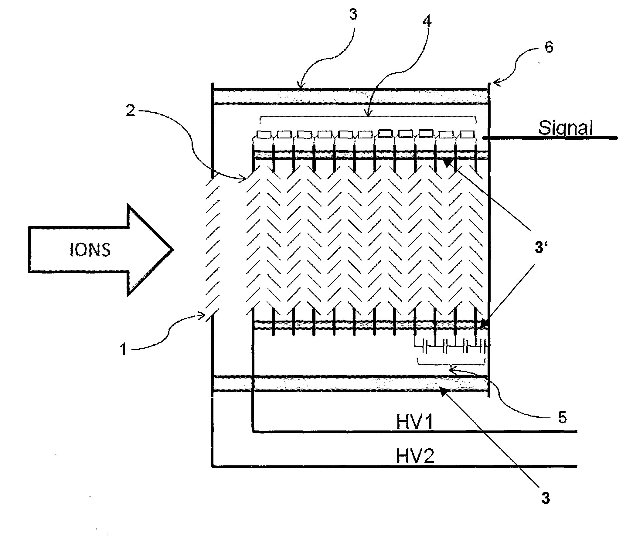
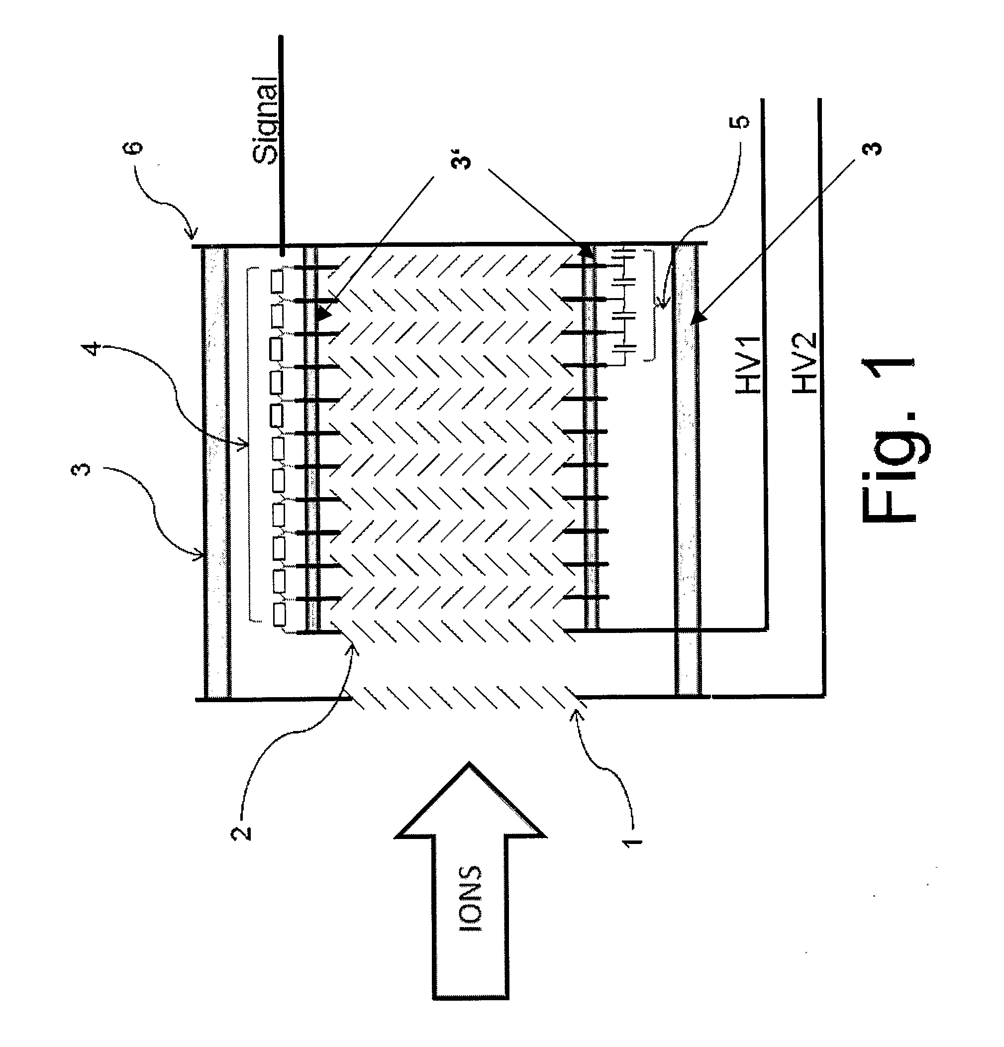
[0035]FIG. 1 shows a detector according a preferred embodiment of the invention in schematic form. After traversing the flight route in the time-of-flight mass spectrometer (not shown), the molecular ions impact onto the conversion dynode (1) of the detector, which is at a high electrical potential. To minimize the time spread due to differing flight lengths of the primary ions before impacting the conversion dynode surface, an extremely thin conversion dynode (1), e.g. 0.5-2 mm, is utilized. With current manufacturing technologies, a thickness of less than 1 mm can be accomplished without great difficulty. Preferably, the conversion dynode is shaped into a geometry, which maximizes the extraction yield of secondary ions and minimizes the extraction time as well as the initial velocity spread of the secondary ions. In the example shown in FIG. 1 the sheets of the dynode, which are at approximately 45° to the ion flight path have a thickness of 0.1 mm or thinner. In this preferred em...


PUM


Abstract

Described here is a detector for measuring heavy mass ions with high sensitivity and low saturation for time-of-flight mass spectrometry and a detector housing for selecting between multiple detectors. It relates to sensitive measuring methods of large masses in the range of about ten thousand to a few million atomic mass units. Specifically it relates to a conversion dynode in a specifically insolated geometry followed by a discrete dynode secondary electron multiplier specifically modified to decrease electron saturation and electronic ringing. Conversion dynode detectors have been used before for time-of-flight mass spectrometry and compared to direct detection with electron multipliers they exhibit superior sensitivity for high-mass, slow-moving macromolecular ions. Using a conversion dynode specifically insolated to a common ground plane has the added capabilities of allowing an increased voltage to be applied to the conversion dynode while maintaining a minimum distance between the conversion dynode and the front of the electron multiplier. This creates faster ion flight time for the secondary ions produced within the detector allowing for higher time resolution and sensitivity from the detector. Also, by adding capacitance as charge buffers to the last few electrodes of a discrete dynode electron multiplier used as a secondary electron multiplier, saturation can be greatly reduced or avoided, which is often a major problem when measuring samples with ions covering a broad mass range. The detector housing described allows multiple detectors to be selected without breaking the vacuum. By keeping all moving mechanical parts inside the vacuum, a more simple, robust and cost effective design can be realized which provides a platform for measuring ions using different detector designs.

Description

FIELD OF THE INVENTION[0001]The present invention relates to the field of time-of-flight (TOF) mass spectrometry (MS), and more particularly to matrix-assisted laser desorption ionization (MALDI) TOF MS. It specifically relates to a detection method and device using a conversion dynode followed by a secondary electron multiplier arranged such to allow for detection of all ions including very massive, slow moving macromolecules. It also relates to a device for housing and rapidly selecting between multiple detectors.BACKGROUND OF THE INVENTION[0002]TOF MS is a fast, efficient and inexpensive technique for discerning the mass of macromolecules. One prominent example for TOF MS is MALDI TOF MS. For MALDI analysis the sample molecules are mixed with a light-absorbing matrix and are vaporized and ionized using a short laser pulse. The molecular ions are then accelerated by a high voltage (+ / −10 to 30 kV) through an evacuated tube of a known length and their arrival times at the opposite ...

Claims


Application Information

Patent Timeline
Patent Type & Authority Applications(United States)
IPC IPC(8): H01J49/40B01D59/44
CPCH01J49/025H01J43/22
Inventor WENZEL, RYANROHLING, ULRICHNAZABAL, ALEXISHILLENKAMP, FRANZ
Owner COVALX
Why Eureka
Try Eureka