Computed radiography system

a radiographic signal and computed technology, applied in the direction of material analysis, measurement devices, instruments, etc., can solve the problems of further increase in manufacturing costs, low shock resistance and cost, and low quantum efficiency of the photocathode utilizing external photoelectric effect, etc., to achieve cost-effective diagnostic read-out, improve signal-to-noise ratio, and reduce radiation exposure dose

Inactive Publication Date: 2011-01-06
T2PHARMA GMBH
View PDF24 Cites 11 Cited by
  • Summary
  • Abstract
  • Description
  • Claims
  • Application Information

AI Technical Summary

Problems solved by technology

Besides its low shock resistance and cost, the quantum efficiency of the photocathode utilizing external photoelectric effect is low: with respect to photostimulated luminescence light in blue wavelength range it is normally as low as about 10 to 20%, whereas the quantum efficiency with respect to photostimulated luminescence light in the red wavelength range is normally about 0.1 to 2%, so that a stimulating light cut filter becomes necessary in order to obtain a satisfactory signal-to-noise ratio (S / N), which means a further increase in manufacturing cost.
Even if each electrode is divided, the area of the photoconductive layer will remain approximately the same area as the sheet and the cost will be increased.
Because the total area of the electrodes remains large, the generation of excessive dark current cannot be avoided, and as capacitance is also great, the problem of a poor S / N ratio remains.
In such a system it is known however that image graininess is deteriorated as sharpness is increased: in the low density area the quantity of X-rays reaching the detector is small and graininess is worse due to quantum noises as compared to that in the high density area in which a quantity of X-rays reaching the detector is large.
1. Pixel resolution which is currently limited, as amorphous silicon, due to its physical properties, does hardly allow to fabricate pixels smaller than some square 100 μm.
2. Panels being of the passive type, i.e. having no “in-pixel amplification” capability, which makes fast imaging, i.e. continuously producing more than 1 image per second, very cumbersome and expensive.
The major problem encountered, is that the (silicon) wafers used in the manufacturing of such detectors are limited in size, that large wafers are very costly and also that the yield of the production process may be low, in that the percentage of good sensors out of a production run decreases very rapidly with increasing size.
The most important drawbacks of this method are that, due to the reduction of the image, a relatively low number of pixels are read out for a large image, resulting in an inferior image quality, due to lower resolution.
A significant portion of the light is lost, leading to lower detection efficiency and / or higher dose to the patient.
This happens because with the current state of the technology, and with demagnifications higher than five to ten times, unless expensive cooling mechanisms are used, the electronic noise from the detector system will be so high in comparison with the electronic signal, that the intrinsic signal-to-noise ratio of the X-ray signal is significantly degraded.
Bulky optics do not allow that the readout system is housed inside e.g. a conventional X-ray cassette as would be desirable in that a system which can be housed in a cassette with the form factor of a conventional X-ray cassette could then be plugged into a conventional X-ray apparatus.
Especially the very accurate mounting poses problems in fabrication and makes such a combination of imaging tiles costly.
It requires high-precision machining technology to cut the silicon very precisely, and high precision machinery is needed to mount the chips together, which makes it costly and complex.
In US-Applications 2001 / 0012412 and 2002 / 0006236 sensors are mounted to but sensitive areas: in one direction the chips overlie each other while in the other direction the chips are butted, but typically the edges of chips can not be brought close together than 50-100 μm, leaving a gap in between that is not light-sensitive and thus could miss essential diagnostic information.
In U.S. Pat. No. 4,467,342 CCD chips for detecting radiant energy have an overlap joint without substantial phase difference occurring at the lap joint, but aligning the sensors accurately is a major difficulty.
CCD sensors further exhibit low efficiency for radiation image sensing.
The system has the drawback that, due to the use of lenses, the apparatus is large and can not be retrofitted in existing machines and X-ray cassettes.
Although these systems have the advantage that no information is missing in between the separate images, such systems however also have a lower light efficiency, and apart for the cost of the multiple systems, these systems usually do not fit in a conventional film-based X-ray system due to their thickness.
U.S. Pat. No. 6,038,286 makes use of mirrors in order to divide the image towards several camera systems, but although its height is somewhat less, that system has nearly the same drawbacks as it uses multiple cameras and overlap seam problems may occur at mirror edges.
However large spaces in between cells are not acceptable for medical applications.
Mechanical systems are however slow, expensive and pose on the long term reliability problems.
Summarized it can be concluded that the current state of the art is so that imagers are either butted and in such case there is always a compromise on the image detail at the seams, while positioning is cumbersome and expensive; or a camera-like approach is used, but in such case the detector assembly rapidly becomes too thick to allow insertion into conventional analog X-ray units.

Method used


Image

  • Computed radiography system
  • Computed radiography system

Examples


examples

[0057]While the present invention will hereinafter be described in connection with preferred embodiments thereof, it will be understood that it is not intended to limit the invention to those embodiments.

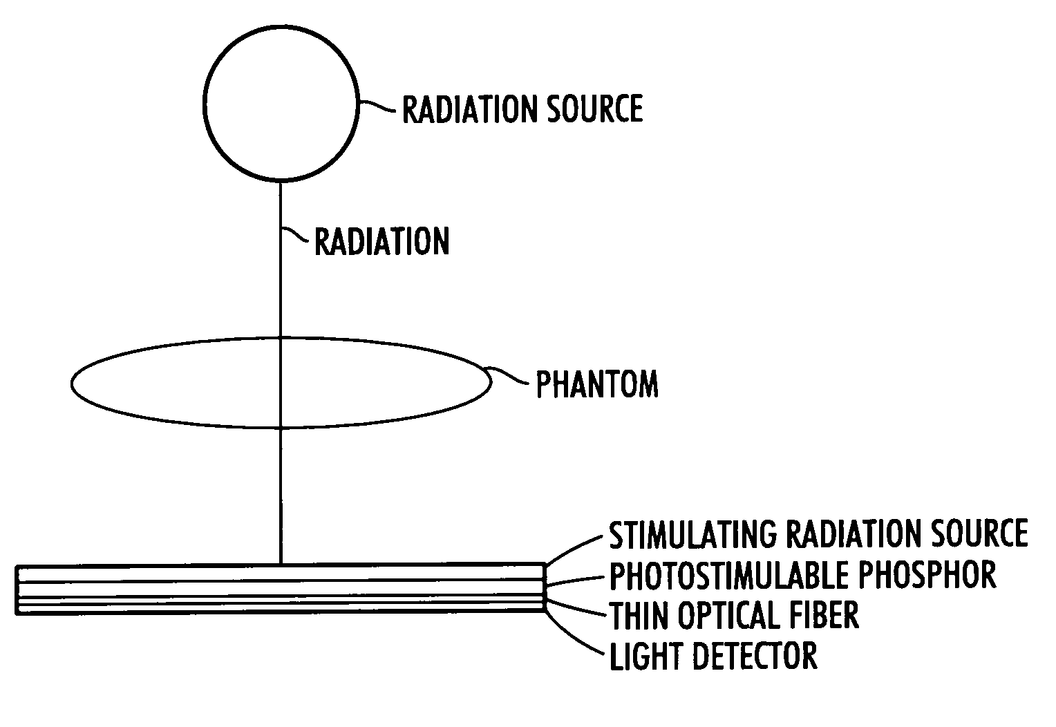
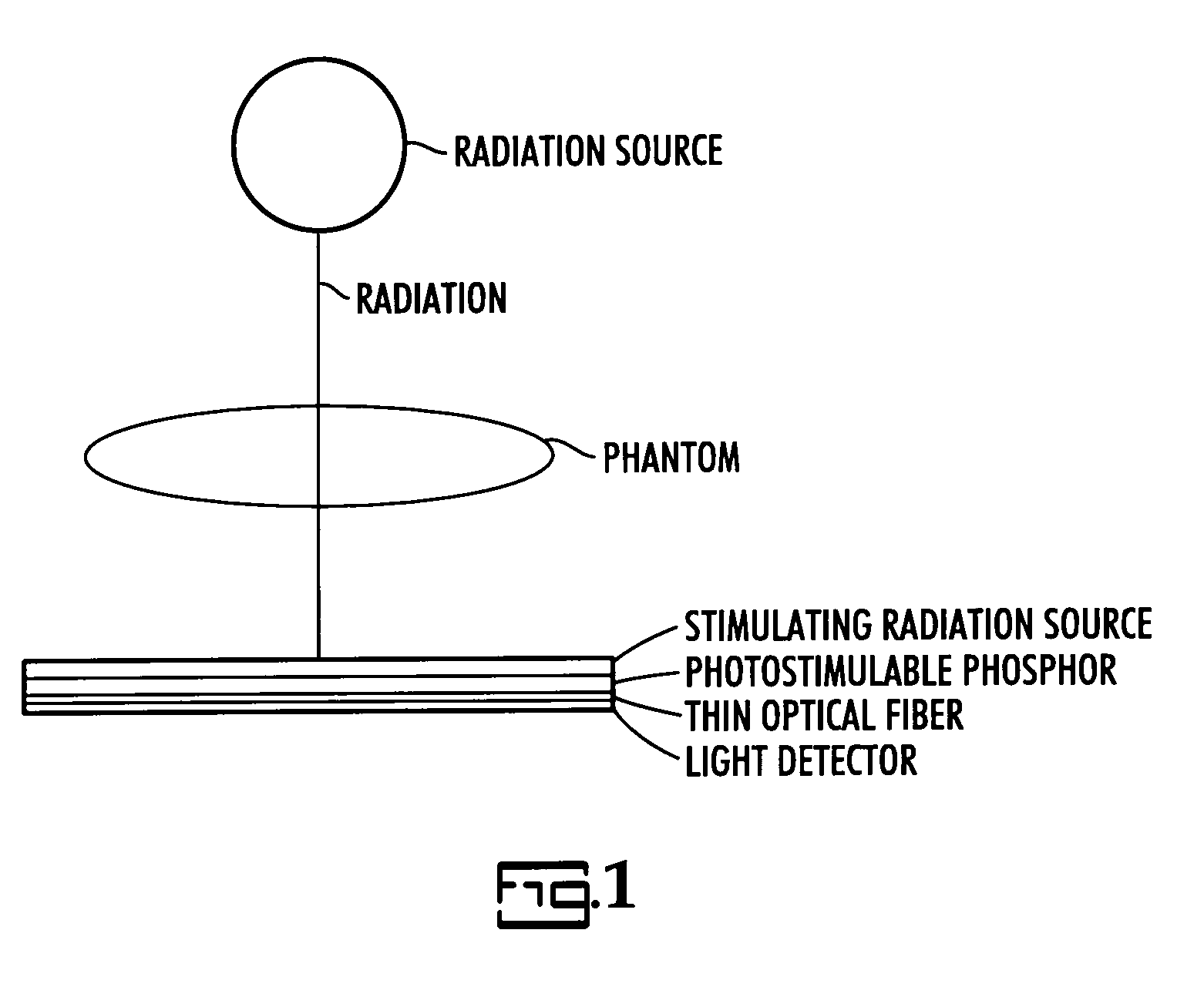
[0058]As has been experimentally set out, while performing only one radiation exposure of the patient schematically illustrated in the FIGURE, the energy emitted by direct radiation detection on the light detector is in the same range as the energy emitted after photostimulation of the storage phosphor plate, bearing the photostimulable phosphor.

[0059]When both the direct energy captured by the first element of the detector and energy set free by photostimulation of energy stored in the photostimulable layer of the detector, present therein as a second element, are superposed, the image signal is clearly enhanced, i.e., about doubled, without an increased noise level.

[0060]As a result thereof an image having an improved signal to noise ratio has been detected. This means that, in ot...


PUM


Abstract

A computed radiography system comprises a radiation detecting system wherein an image is formed by the steps of (1) exposing an object to radiation; (2) forming a first digitized image directly captured from said radiation by a detector; (3) storing said digitized image from said radiation on an intermediate medium; (4) forming a latent image originating from the same radiation, as an image stored in a photostimulable phosphor layer, and (5) retrieving said directly captured digitized image and superposing it onto a digitized image originating from said latent image in said photostimulable phosphor layer after photostimulation of said phosphor layer with radiation having a lower energy than the said exposure radiation.

Description

CROSS-REFERENCE TO RELATED PATENT APPLICATIONS[0001]This application claims the benefit of U.S. Provisional Application No. 60 / 872,728 filed Dec. 4, 2006, which is incorporated by reference.FIELD OF THE INVENTION[0002]The present invention relates to a solution for processing computed radiographic signals in order to obtain an image having a better signal to noise ratio. More specifically the invention is related to the use of photostimulable phosphor screens in a system providing improved read-out with an increased DQE and allowing a lower exposure dose.BACKGROUND OF THE INVENTION[0003]All of the patent and literature references hereinafter are incorporated herein by reference.[0004]A well-known use of phosphors is in the production of X-ray images. In a conventional radiographic system an X-ray radiograph is obtained by X-rays transmitted image-wise through an object and converted into light of corresponding intensity in a so-called intensifying screen (X-ray conversion screen) wh...

Claims


Application Information

Patent Timeline
Patent Type & Authority Applications(United States)
IPC IPC(8): G01T1/208
CPCG01T1/2016G01T1/2014
Inventor STRUYE, LUC
Owner T2PHARMA GMBH
Why Eureka
Try Eureka