Multi-shot Connector Assembly and Method of Manufacture

a multi-shot, connector technology, applied in the direction of coupling device connection, foundry pattern, foundry moulding apparatus, etc., can solve the problems of significant material waste, high-precision machining/turning equipment, manufacturing, inventory and delivery coordination to the assembly area of each of the plurality of separate elements is a significant additional manufacturing cost, and the manufacturing process is complex and laborious

Inactive Publication Date: 2011-01-06
ANDREW LLC
View PDF28 Cites 63 Cited by
  • Summary
  • Abstract
  • Description
  • Claims
  • Application Information

AI Technical Summary

Problems solved by technology

Machining of metal elements from metal bar stock typically results in significant material waste and requires sophisticated high precision machining / turning equipment and skilled operators for same.
However, the separate metal and polymeric elements must each be separately formed, any flashing removed or other rework performed and each of the separate elements assembled together by labor intensive press fit and / or hand assembly operations to complete the connector assembly.
Manufacture, quality control, inventory and delivery coordination to the assembly area of each of the plurality of separate elements is a significant additional manufacturing cost.
Further, a problem resulting in a delivery delay of any one of the multiple separate elements and or damage or loss during field assembly renders the remainder of the connector inoperable.
Therefore, the connector is incompatible with smooth or annular corrugated solid outer conductor coaxial cable, is expensive to manufacture and time consuming to install.
The mounting of the connectors upon holes formed in the base or other flange may require tool access to both sides of the mounting point, creating an overall increase in the antenna size, complicating assembly and / or introducing additional environmental sealing issues.

Method used


Image

  • Multi-shot Connector Assembly and Method of Manufacture
  • Multi-shot Connector Assembly and Method of Manufacture
  • Multi-shot Connector Assembly and Method of Manufacture

Examples


Embodiment Construction

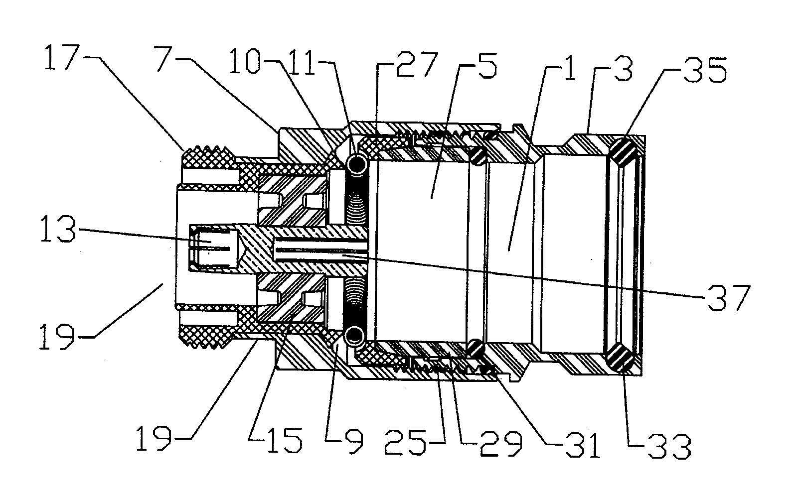
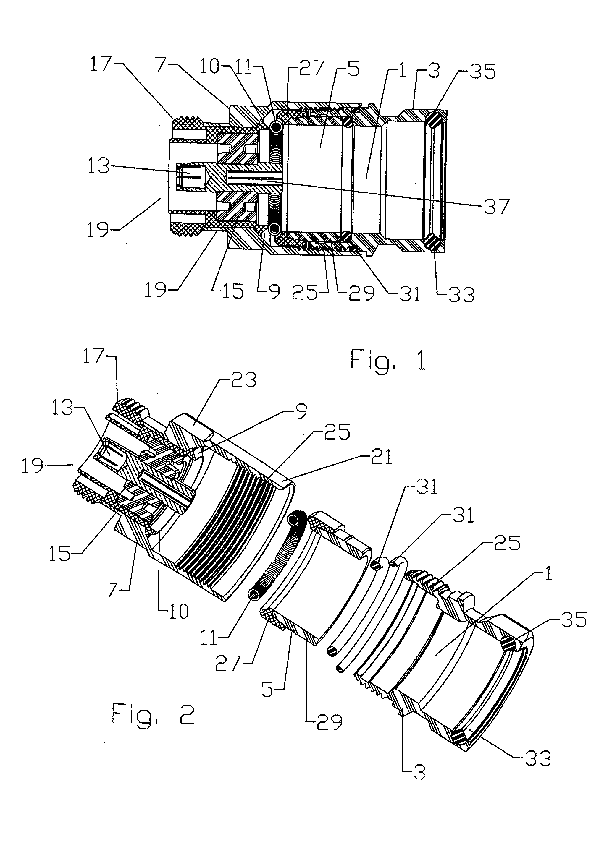
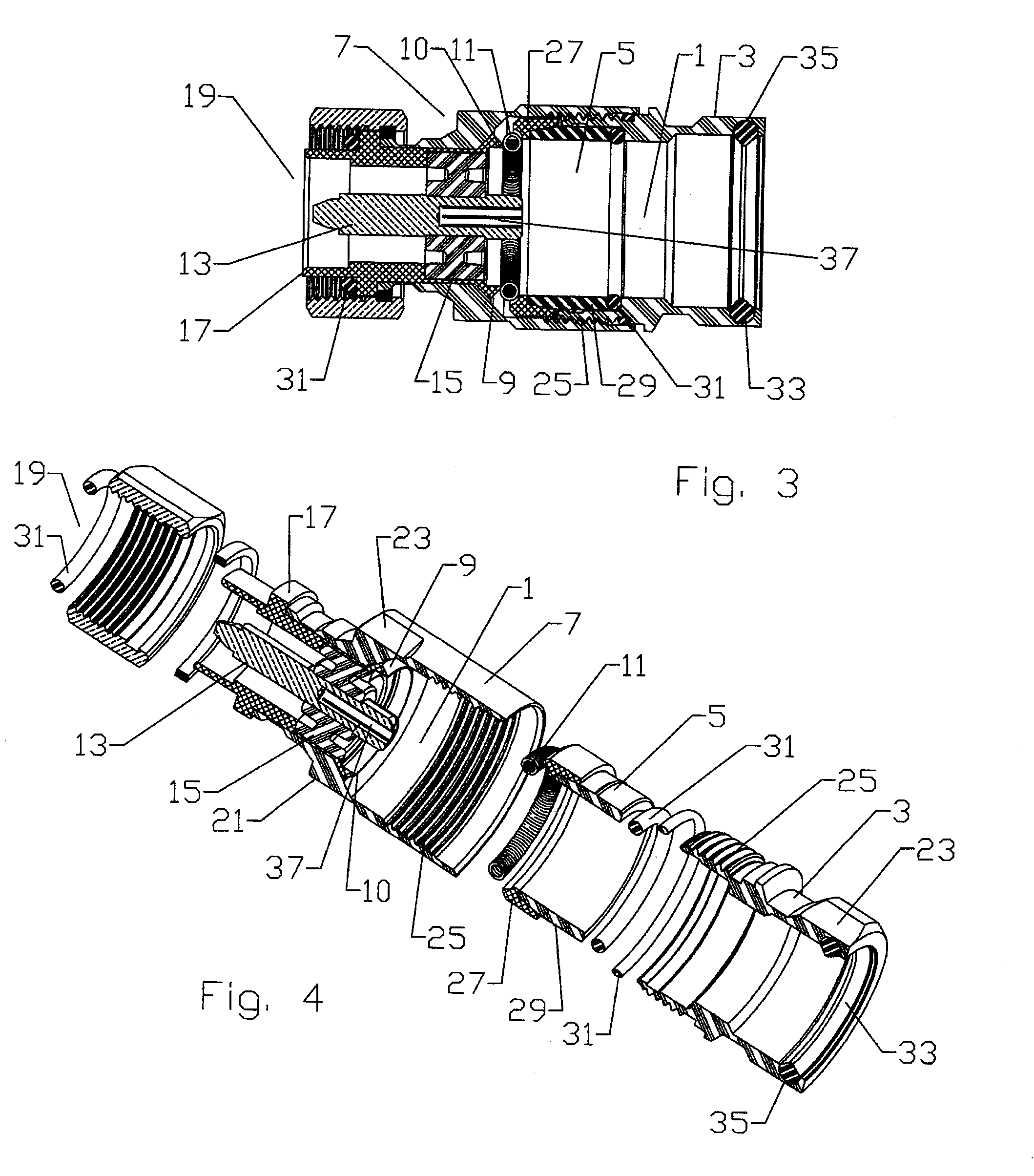
[0041]The inventor has recognized that injection moldable metal compositions, usable with conventional polymeric injection molding equipment, enables manufacture of multi-shot combination metal and polymeric material electrical connector assemblies. Thereby, numerous manufacturing steps and the prior need for additional seals between separate elements may be eliminated to realize a significant materials and manufacturing cost savings.

[0042]An example of an injection moldable metal composition is “Xyloy”™ M950 available from Cool Poly, Inc. of Warwick, R.I., US. “Xyloy”™ M950 comprises an aluminum and zinc composition delivered in pellet form to injection molding equipment in the same manner as raw polymer pellets. Because the melting point of zinc is comparatively low, a combination of aluminum and zinc results in an alloy with a low enough melting point and viscosity characteristics suitable for use in polymeric injection molding machines without requiring any modification thereto....


PUM

PropertyMeasurementUnit
temperatureaaaaaaaaaa
melting pointsaaaaaaaaaa
outer diameteraaaaaaaaaa

Abstract

A coaxial cable connector formed via multi-shot injection molding has a body formed by multiple injection molding layers of different injection moldable materials about a central inner contact to form an integral connector body. The connector body is provided with a coaxial dielectric spacer of dielectric polymer surrounding the inner contact; a coaxial inner body of injection molded metal composition surrounding an outer diameter of the dielectric spacer; and an outer body of polymer surrounding the inner body. Interlock features provide axial and/or rotational interlock between the layers of the connector.

Description

CROSS REFERENCE TO RELATED APPLICATIONS[0001]This application is a continuation-in-part of commonly owned co-pending U.S. Utility patent application Ser. No. 12 / 559,176, titled “Multi-shot Coaxial Connector and Method of Manufacture”, filed Sep. 14, 2009 by Kendrick Van Swearingen and Nahid Islam, currently pending, which is a continuation-in-part of commonly owned U.S. Utility patent application Ser. No. 12 / 191,922, titled “Multi-shot Coaxial Connector and Method of Manufacture”, filed Aug. 14, 2008 by Kendrick Van Swearingen, patented as U.S. Pat. No. 7,607,942 on Oct. 27, 2009.BACKGROUND OF THE INVENTION[0002]1. Field of the Invention[0003]The invention relates to an electrical connector. More particularly the invention relates to a lightweight and cost efficient electrical connector assembly with significant material and manufacturing efficiencies realized by application of multi-shot injection molding technology.[0004]2. Description of Related Art[0005]Electrical connectors are...

Claims


Application Information

Patent Timeline
Patent Type & Authority Applications(United States)
IPC IPC(8): H01R9/05B22D19/00B22D17/00B22D25/02
CPCB29C45/14639H01R2201/02B29C2045/1696H01Q1/246H01R9/0521H01R13/405H01R13/504H01R13/512H01R13/5205H01R13/521H01R13/5219H01R13/622H01R13/74H01R24/40H01R43/18H01R43/24H01R2103/00H01R2107/00B29C45/16
Inventor VAN SWEARINGEN, KENDRICKLE, QUOC M.SCHMUTZLER, STEVE
Owner ANDREW LLC
Why Eureka
Try Eureka