Carbon Dioxide Absorber And Regeneration Assemblies Useful For Power Plant Flue Gas

a technology of carbon dioxide absorber and power plant flue gas, which is applied in the direction of emission prevention, lighting and heating apparatus, separation processes, etc., can solve the problems of unfeasible technology, difficult to apply in practice, and inapplicability of bubbling fluidized bed to power plant systems, etc., to limit or prevent localized overheating of sorben

Active Publication Date: 2011-01-13
THE SOUTHERN CO
View PDF12 Cites 41 Cited by
  • Summary
  • Abstract
  • Description
  • Claims
  • Application Information

AI Technical Summary

Benefits of technology

[0057]The seal pot acts as a non-mechanical regulating valve controlling the flow of sorbent to regenerator through aeration flow control, and at the same time limits or prevents reverse flow of regenerator gases into the absorber assembly, and vice versa.
[0058]The...

Problems solved by technology

Yet, these conventional contactors are economically unfeasible and difficult to apply in practice to the absorption of CO2 from power plant flue gas for at least the following reasons: (i) the volume of the flue gas from a power plant is large—an 880 MWe coal-burning plant can generate flue gas at a rate of more than 120 million ft3/hr; (ii) the large volumetric flow rates of the flue gas essentially rules out the possibility of using a moving bed absorber, which requires the gas velocity to be below approximately 3 ft/s; and (iii) a large number of absorbers and regenerators would have to be installed and operated to handle the flue gas from a modern power plant at such low velocities.
Using a bubbling fluidized bed would cause the same problems as using a moving bed absorber and the regenerator, because the gas velocity in a bubbling bed needs to be below approximately 5 ft/s under most circumstances.
As sorbents are relatively expensive, any excessive attrition can render the technology economically unfeasible.
Therefore, a bubbling fluidized bed is not applicable with power plant systems.
A further complication in using solid sorbents for CO2 removal is the need for the gas to remain in contact with the sorbent for a few seconds even when the absorption kinetics are relatively fast.
Such relatively long contact times makes it difficult to use a fabric filter as an effective contactor for the CO2 absorption, as the gas is in contact with the solid cake only for a fraction of a second when the gas flows through the fabric contactor.
Another issue that arises with absorption of CO2 in flue gas by solid sorbents is the large volume of CO2 generated from a power plant and relatively low absorption capacity per unit weight of the sorbent.
It is impractical to use the sorbent in a once-through process.
Handling millions of pounds of sorbent circulating at a rate of tens of millions of lbs/hr is a serious challenge for existing reactors as absorbers and regenerators.
The challen...

Method used


Image

  • Carbon Dioxide Absorber And Regeneration Assemblies Useful For Power Plant Flue Gas
  • Carbon Dioxide Absorber And Regeneration Assemblies Useful For Power Plant Flue Gas
  • Carbon Dioxide Absorber And Regeneration Assemblies Useful For Power Plant Flue Gas

Examples


example

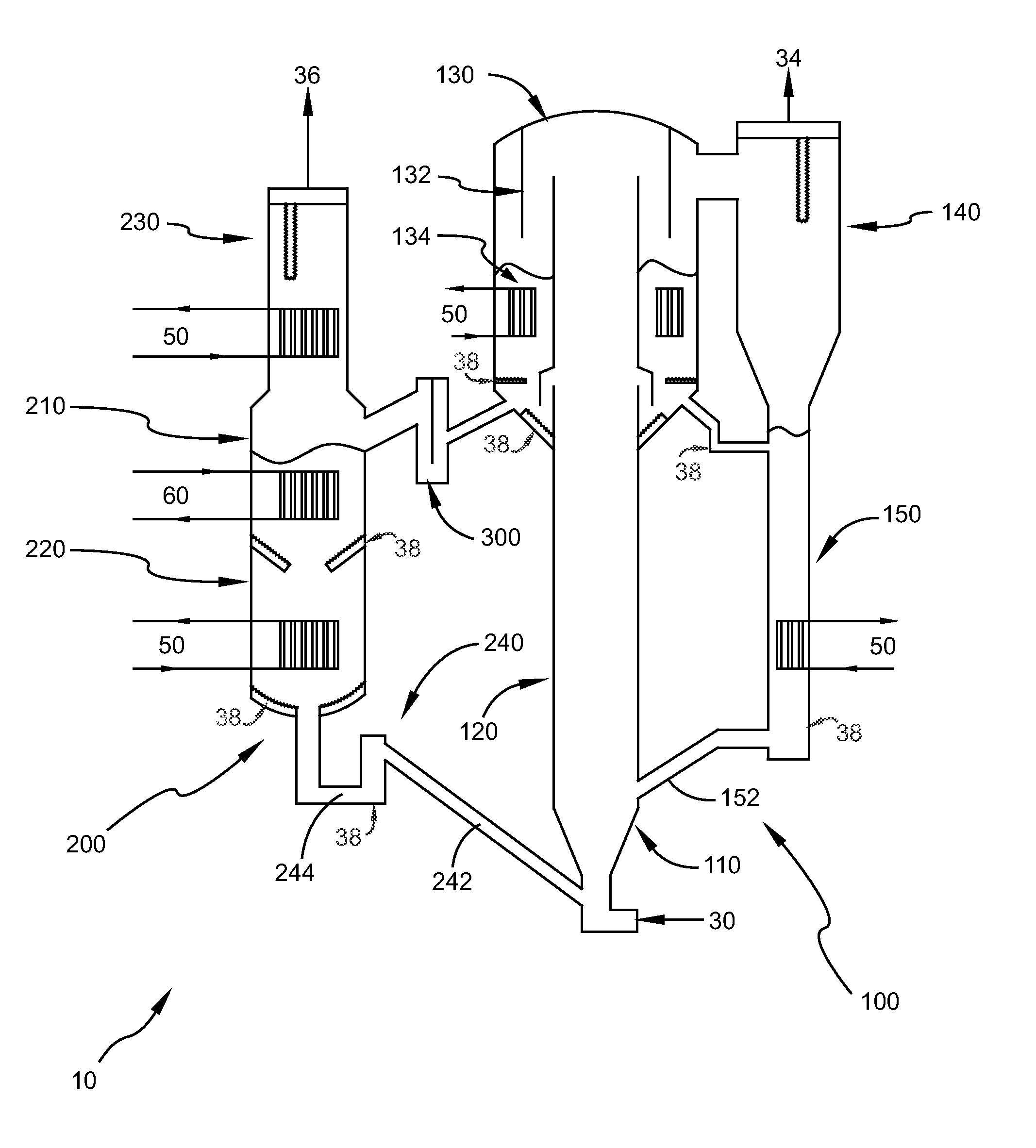
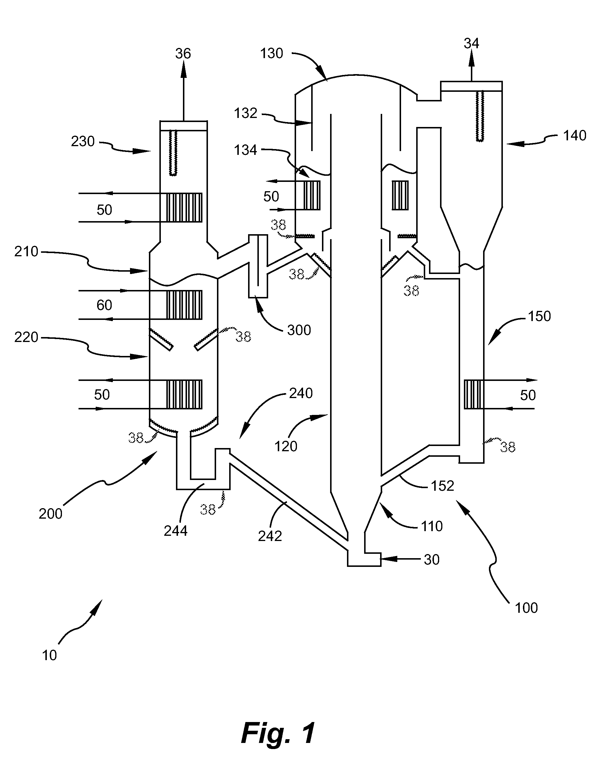
[0114]As an example of enumerating the concepts of present invention, a test apparatus 400, as shown in FIG. 7, has been built, and sorbents for their CO2 capture ability has been tested on a continuous absorption and regeneration basis. This apparatus includes the major embodiments of the present invention, including the absorber assembly (as in FIG. 1), ICFB 130 (as in FIG. 1) and fluid bed regeneration of sorbent in annular space (as in FIG. 4).

[0115]In the test apparatus 400, as many different types of sorbent are being tested (both with low and high exothermic heat releases), the absorber riser section 120 was surrounded by a jacket cooler 122 to remove exothermic heat from absorption of CO2. For industrial scale systems, the heat removal will be achieved by injecting the cooled, partially spent sorbent to the bottom of the absorber assembly 100 (FIG. 1 for sorbents with slower kinetics), or at various elevations along the height of the absorber assembly 100 (FIG. 4 for sorbent...


PUM


Abstract

Disclosed are apparatus and method to treat large amounts of flue gas from a pulverized coal combustion power plant. The flue gas is contacted with solid sorbents to selectively absorb CO2, which is then released as a nearly pure CO2 gas stream upon regeneration at higher temperature. The method is capable of handling the necessary sorbent circulation rates of tens of millions of lbs/hr to separate CO2 from a power plant's flue gas stream. Because pressurizing large amounts of flue gas is cost prohibitive, the method of this invention minimizes the overall pressure drop in the absorption section to less than 25 inches of water column. The internal circulation of sorbent within the absorber assembly in the proposed method not only minimizes temperature increases in the absorber to less than 25° F., but also increases the CO2 concentration in the sorbent to near saturation levels. Saturating the sorbent with CO2 in the absorber section minimizes the heat energy needed for sorbent regeneration. The commercial embodiments of the proposed method can be optimized for sorbents with slower or faster absorption kinetics, low or high heat release rates, low or high saturation capacities and slower or faster regeneration kinetics.

Description

CROSS REFERENCE TO RELATED APPLICATION[0001]This application claims benefit under 35 USC §119(e) of U.S. Provisional Patent Application Ser. No. 61 / 224,629 filed 10 Jul. 2009, which application is hereby incorporated fully by reference.STATEMENT REGARDING FEDERALLY SPONSORED RESEARCH OR DEVELOPMENT[0002]This invention was made with some Government support under Cooperative Agreement Number DE-NT0000749 awarded by the United States Department of Energy. The Government has certain rights in this invention.BACKGROUND OF THE INVENTION[0003]1. Field of the Invention[0004]The present invention is directed generally towards a species transfer system. In particular, the present invention is designed to absorb a specific species, CO2, from large amounts of flue gas exiting a power plant, and transfer the species to a controlled outlet stream, and ultimately transforming the flue gas into a CO2 lean gas stream. The combustion of carbonaceous materials using air as an oxidant generates a combu...

Claims


Application Information

Patent Timeline
IPC IPC(8): B01D53/04
CPCB01D53/08B01D53/62B01D2257/504Y02C10/08F23J2219/60Y02C10/04Y02C10/06F23J2215/50Y02A50/20Y02C20/40
Inventor VIMALCHAND, PANNALALLIU, GUOHAIPENG, WAN WANG
Owner THE SOUTHERN CO
Why Eureka
Try Eureka