Circulating fluidized bed catalytic combustion system for treating organic waste gas

A circulating fluidized bed and catalytic combustion technology, applied in the direction of combustion method, combustion type, incinerator, etc., can solve the problems of complex system structure and operation, achieve the effect of improving fluidization quality, large reaction surface area, and preventing heat accumulation

Pending Publication Date: 2020-10-02
JIANGSU NANFANG COATING & ENVIRONMENT PROTECTION EQUIP +1
View PDF2 Cites 1 Cited by
  • Summary
  • Abstract
  • Description
  • Claims
  • Application Information

AI Technical Summary

Problems solved by technology

This invention can realize continuous operation to treat high-concentration organic waste gas and prevent heat accumulation, but two sets of fluidized bed devices are required, the system structure and operation are complicated, and post-treatment of concentrated organic waste gas is still required

Method used


Image

  • Circulating fluidized bed catalytic combustion system for treating organic waste gas
  • Circulating fluidized bed catalytic combustion system for treating organic waste gas
  • Circulating fluidized bed catalytic combustion system for treating organic waste gas

Examples


Embodiment 1

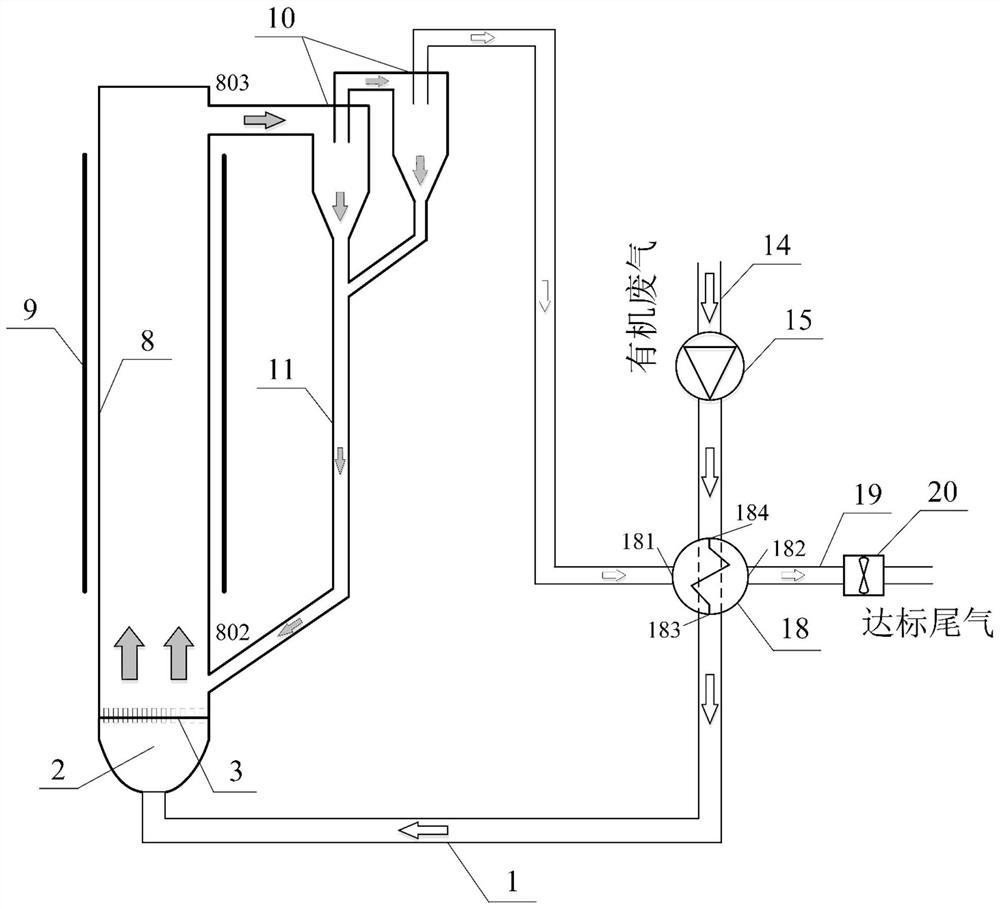
[0044] Such as figure 1 A circulating fluidized bed catalytic combustion system 1 for treating organic waste gas shown, the system includes:

[0045] A circulating fluidized bed catalytic combustion furnace, the circulating fluidized bed catalytic combustion furnace includes a fluidization air chamber 2, an air distribution plate 3, a riser 8, a separator 10 and a dipleg 11, wherein the upper part of the riser 8 is The feed port 803 is connected to the feed port of the separator 10, the lower discharge port of the separator 10 is connected to the upper end feed port of the material leg 11, and the lower end discharge port of the material leg 11 is connected to the riser return pipe 802, and the circulation Insulation of the whole circuit of the fluidized bed catalytic combustion furnace;

[0046] The heat recovery and heating device, the heat recovery and heating device includes a heat exchanger 18 and an electric heating component 9, wherein the heat exchanger 18 is a partit...

Embodiment 2

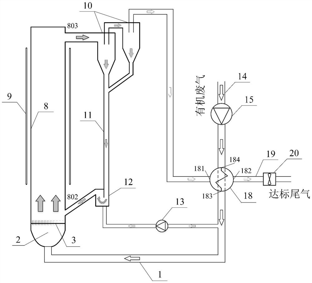
[0061] Such as figure 2 shown in figure 1 Based on the illustrated circulating fluidized bed catalytic combustion system for treating organic waste gas, an improved circulating fluidized bed catalytic combustion system for treating organic waste gas II is also provided. In addition to the components in system one, system two also includes a return device, also known as a particle circulation control device, whose function is not only to adjust and control the particle circulation to achieve the required particle circulation rate; "Backchannel" flow to separator 10. The material return device includes a material return valve 12, a material return air booster fan 13 and a corresponding connecting air duct, wherein the material return valve 21 is between the material outlet at the lower end of the material leg 11 and the inlet of the riser return material pipe 802, and A branch pipe is branched out from the riser inlet main pipe 1 and connected with the air inlet of the return...

Embodiment 3

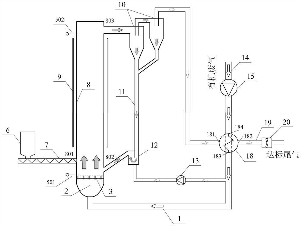
[0065] Such as image 3 shown in figure 2Based on the illustrated circulating fluidized bed catalytic combustion system for treating organic waste gas, an improved circulating fluidized bed catalytic combustion system for treating organic waste gas is also provided III. In addition to the components in system two, system three also includes silo 6, high-pressure screw feeder 7, lower pressure measuring point 501, upper pressure measuring point 502, and a high-pressure screw is provided at the feed port 801 of the front wall of the riser 8. The feeder 7 and the high-pressure screw feeder 7 are arranged below the silo 6 , the lower pressure measuring point 501 is arranged on the upper side of the air distribution plate 3 , and the upper pressure measuring point 502 is arranged on the top of the cavity of the riser 8 .

[0066] In this embodiment, based on the use method of system three, in addition to the steps described in system two, it also includes feeding and material inv...


PUM


Abstract

The invention discloses a circulating fluidized bed catalytic combustion system for treating organic waste gas, and belongs to the field of environmental protection. The system comprises a circulatingfluidized bed catalytic combustion furnace, a heat exchanger (18) and an electric heating component (9); the circulating fluidized bed catalytic combustion furnace comprises a fluidized air chamber (2), an air distribution plate (3) and a riser (8); the fluidized air chamber (2) is connected with an organic waste gas header pipe (14) provided with a fluidized air blower (15) through a riser air inlet header pipe (1); an upper discharging opening (803) of the riser (8) with the electric heating component (9) distributed around is connected with a feeding opening of a separator (10); a discharging opening of the separator (10) is connected with a feeding opening of a dip-leg (11); a discharging opening of the dip-leg (11) is connected with a riser return pipe (802); and an air exhausting opening of the separator (10) is connected with the heat exchanger (18) through a pipeline. The system is high in removal rate and high in heat utilization rate and can run continuously and stably for along time.

Description

technical field [0001] The invention relates to the field of organic waste gas treatment, in particular to a circulating fluidized bed catalytic combustion system for treating organic waste gas. Background technique [0002] Volatile organic compounds (Volatile Organic Compounds, VOCs) are one of the important sources of air pollution. There are many kinds of them, and they are very harmful to the environment and human beings. VOCs come from a wide range of sources, such as tobacco industry, printing industry, automobile industry, decoration industry, pharmaceutical industry, textile industry, chemical industry, etc., in the process of manufacturing, printing, spraying, cleaning, transportation, etc. VOCs may be generated. At present, the generation and discharge of organic waste gas in production activities is unavoidable, so the treatment technology of such pollutants is particularly important. [0003] The treatment technology of organic waste gas can be roughly divided ...

Claims


Application Information

Patent Timeline
Patent Type & Authority Applications(China)
IPC IPC(8): F23G7/07F23G5/02F23G5/10F23G5/46F23G5/44F23G5/50
CPCF23G5/02F23G5/10F23G5/44F23G5/46F23G5/50F23G7/07F23G2201/60F23G2202/60F23G2203/50F23G2204/20F23G2206/10F23G2209/14F23G2900/50213
Inventor 李爱军柯希玮
Owner JIANGSU NANFANG COATING & ENVIRONMENT PROTECTION EQUIP
Why Eureka
Try Eureka