Optical tomographic imaging apparatus

a tomographic imaging and optical technology, applied in the field of optical tomographic imaging apparatus, can solve the problems of taking time to acquire a plurality of images, apparatus in the conventional example, etc., and achieve the effect of reducing the burden on the subj

Active Publication Date: 2011-02-03
CANON KK
View PDF14 Cites 29 Cited by
  • Summary
  • Abstract
  • Description
  • Claims
  • Application Information

AI Technical Summary

Benefits of technology

[0025]On the other hand, with opthalmologic diagnosis and the like with an optical tomographic imaging apparatus, there is a strong demand for reducing imaging time in order to alleviate the burden on subjects being tested. As described above, apparatuses in conventional examples do not consider methods for reducing imaging time when performing high-resolution tomographic imaging by OCT.
[0032]Consequently, an optical tomographic imaging apparatus that enables tomographic imaging of a retina with a reduced burden on a subject during opthalmologic diagnosis and the like can be provided.

Problems solved by technology

However, the apparatuses in the conventional examples described above have the following problems.
In addition, Japanese Patent Application Laid-Open No. 2007-101250 fails to disclose methods for achieving a higher speed during image composition and therefore takes time to acquire a plurality of images and to combine images.

Method used


Image

  • Optical tomographic imaging apparatus
  • Optical tomographic imaging apparatus
  • Optical tomographic imaging apparatus

Examples


embodiments

First Embodiment

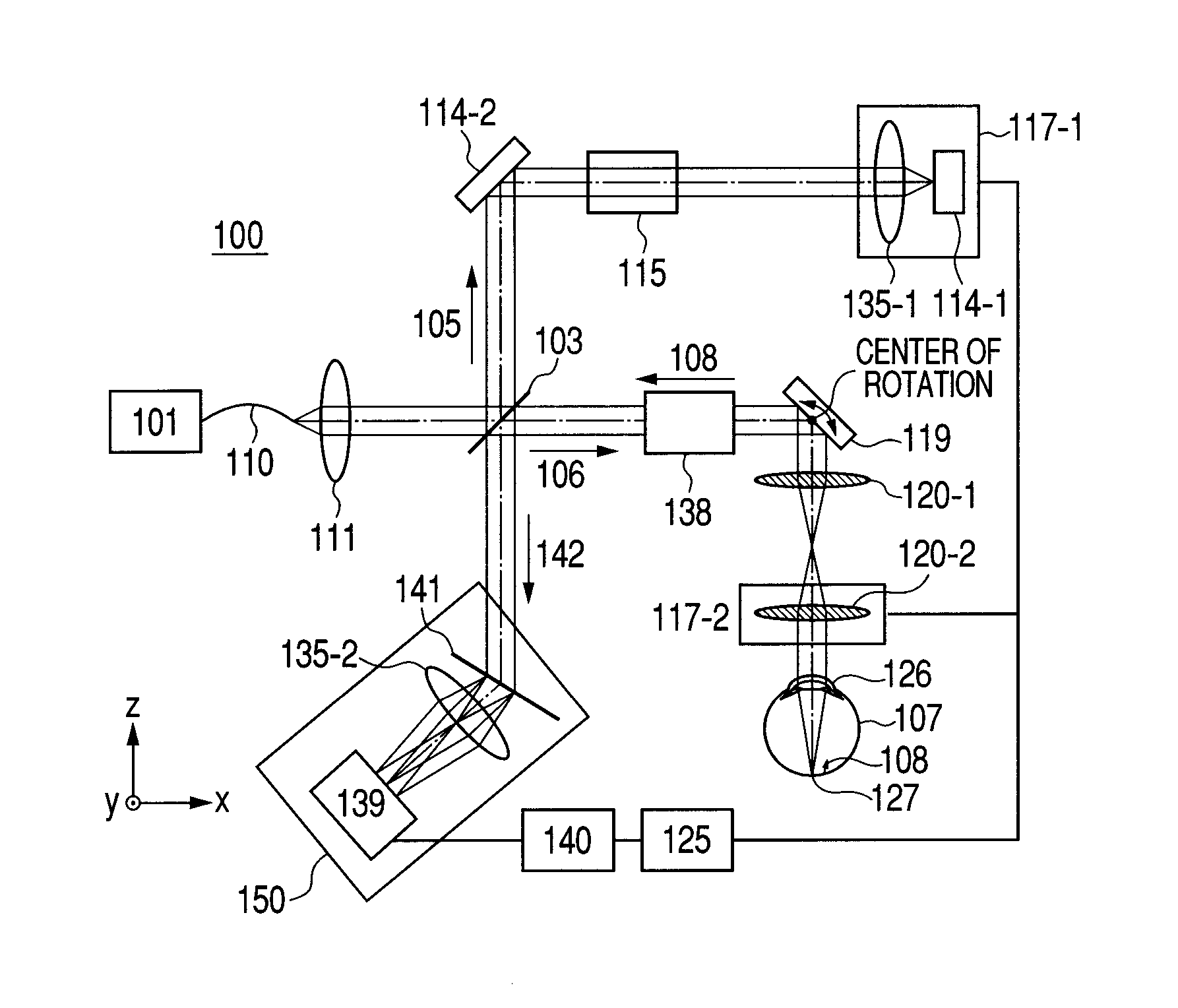
[0042]In the first embodiment, an optical tomographic imaging apparatus to which the present invention is applied will be described with reference to FIG. 1A.

[0043]FIG. 1A illustrates an optical tomographic imaging apparatus 100, a light source 101, a beam splitter 103, a reference beam 105, a measuring beam 106, a combined beam 142, and an eye to be inspected 107 that is an object.

[0044]Also illustrated are a return beam 108, a single-mode fiber 110, lenses 111, 120 and 135, and a mirror 114.

[0045]FIG. 1A also illustrates a dispersion compensating glass 115, an electrically-powered stage 117, an X-Y-scanner 119, and a personal computer 125.

[0046]Also illustrated are a cornea 126, a retina 127, a variable beam expander 136 that is a beam diameter changing unit, a spectroscope 150 that is a detection unit, a line camera 139, a frame grabber 140, and a transmissive grating 141 that is a spectroscopic unit.

[0047]The optical tomographic imaging apparatus according to the...

second embodiment

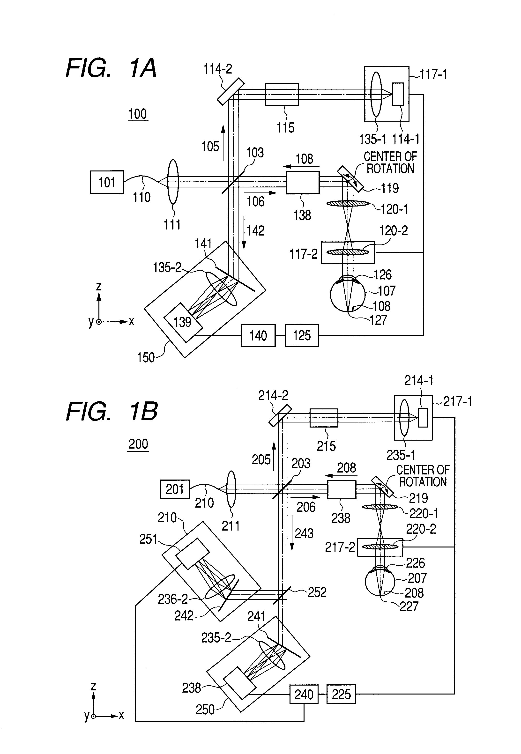
[0149]Next, an optical tomographic imaging apparatus for Fourier domain optical coherence tomography according to a second embodiment will be described with reference to FIG. 1B.

[0150]Unlike the first embodiment, the present embodiment includes a plurality of detection units, wherein each of the detection units has a spectroscope with a different configuration.

[0151]Otherwise, the configuration as an apparatus is similar to the first embodiment. Accordingly, descriptions of overlapping portions will be omitted.

[0152]First, a general configuration of an overall optical system of the optical tomographic imaging apparatus according to the present embodiment will be described.

[0153]FIG. 1B illustrates an optical tomographic imaging apparatus 200, a light source 201, beam splitters 203 and 252, a reference beam 205, a measuring beam 206, a combined beam (interference light) 243, an eye to be inspected 207, a return beam 208, and a single-mode fiber 210.

[0154]Also illustrated are lenses 2...

third embodiment

[0188]Next, an optical tomographic imaging apparatus for Fourier domain optical coherence tomography according to a third embodiment will be described with reference to FIGS. 4A to 4E.

[0189]Compared to the first embodiment, the present embodiment adopts a zone focusing method in which, in a high-resolution mode, focus positions are changed in stages and a plurality of B-scan images obtained at respective positions is pieced together.

[0190]Accordingly, a configuration can be realized in which a tomographic image acquired during a narrow depth of focus (DOF) in the high-resolution mode can be obtained to a deeper position.

[0191]Otherwise, the configuration as an apparatus is similar to the first embodiment. As such, descriptions of overlapping portions will be omitted.

[0192]First, a general configuration of an overall optical system of the optical tomographic imaging apparatus according to the present embodiment will be described.

[0193]FIG. 4A illustrates an optical tomographic imagin...


PUM


Abstract

An optical tomographic imaging apparatus is provided which includes a low-resolution mode for rough imaging and a high-resolution mode for obtaining detailed images. In particular, an optical tomographic imaging apparatus is provided which enables tomographic imaging during a high-resolution mode to be performed at higher speeds. An imaging apparatus according to the present invention captures an optical interference tomographic image based on a combined beam that combines a return beam from an object irradiated by a measuring beam and a reference beam corresponding to the measuring beam. The imaging apparatus according to the present invention further includes a beam diameter changing unit for changing a beam diameter of the measuring beam. Furthermore, the imaging apparatus according to the present invention includes a detection unit configured to detect the combined beam at a resolution according to the beam diameter.

Description

BACKGROUND OF THE INVENTION[0001]1. Field of the Invention[0002]The present invention relates to an optical tomographic imaging apparatus, and particularly to an optical tomographic imaging apparatus used in opthalmologic diagnosis and treatment and the like.[0003]2. Description of the Related Art[0004]Various opthalmologic devices that utilize optical devices are in use today.[0005]For example, various devices such as an anterior ocular segment photographing device, a fundus camera, and a scanning laser opthalmoscope (SLO) are used as optical devices for observing the eye.[0006]Among such optical devices, an optical tomographic imaging apparatus based on optical coherence tomography (hereinafter referred to as OCT) that utilizes multi-wavelength lightwave interference is capable of obtaining a high-resolution tomographic image of a sample.[0007]OCTs are becoming indispensable opthalmologic devices at outpatient retina specialists.[0008]According to the optical tomographic imaging a...

Claims


Application Information

Patent Timeline
Patent Type & Authority Applications(United States)
IPC IPC(8): G01J3/45G01B9/02
CPCA61B3/102G01N21/4795A61B5/0073A61B5/0066
Inventor MUTO, KENJIKITAMURA, TAKESHI
Owner CANON KK
Why Eureka
Try Eureka