Method of forming a thermally stable diamond cutting element

a cutting element and thermally stable technology, applied in the field of thermally stable diamond cutting element formation, can solve the problems of structural disintegration in the pcd layer, limiting the service life of the cutting element, and introducing thermal stresses to the pcd material, so as to facilitate the leaching of the cutting surface, improve the thermal characteristics, and reduce the thermal stress of the material

Inactive Publication Date: 2011-02-10
SMITH INT INC
View PDF99 Cites 48 Cited by
  • Summary
  • Abstract
  • Description
  • Claims
  • Application Information

AI Technical Summary

Benefits of technology

[0012]Diamond bonded constructions prepared according to principles of the invention have improved thermal characteristics, as the infiltrated TSP material is more fully infiltrated during the bonding step. The improved infiltration of the TSP reduces thermal stresses in the material and facilitates leaching of the cutting surface, which in turn provides a cutting surface with improved properties of thermal stability, abrasion resistance, and wear resistance while maintaining a high bond strength.

Problems solved by technology

However, the presence of the catalyst material in the sintered PCD material introduces thermal stresses to the PCD material, when the PCD material is heated, as for example by frictional heating during use, as the catalyst typically has a higher coefficient of thermal expansion than does the PCD material.
Thus, the sintered PCD is subject to thermal stresses, which limit the service life of the cutting element.
Furthermore, when the operating or servicing temperature reaches or exceeds 700° C., the diamond structure in the PCD layer converts back to graphite with the presence of Group VIII catalyst material, causing structural disintegration in the PCD layer.
The presence of these residuals hinders the infiltration of cobalt (or other infiltrant) into the TSP during bonding.
The result is TSP material that is only partially infiltrated or not properly infiltrated, as the infiltration path is blocked by those residual materials.
Partial infiltration is problematic, as thermal and other stresses build in the non-infiltrated region of the TSP.
Partial infiltration also makes leaching more difficult, and weakens the bond between the TSP layer and the substrate.
Partial infiltration also creates inconsistencies in the performance of the TSP cutting elements.

Method used


Image

  • Method of forming a thermally stable diamond cutting element
  • Method of forming a thermally stable diamond cutting element
  • Method of forming a thermally stable diamond cutting element

Examples


Embodiment Construction

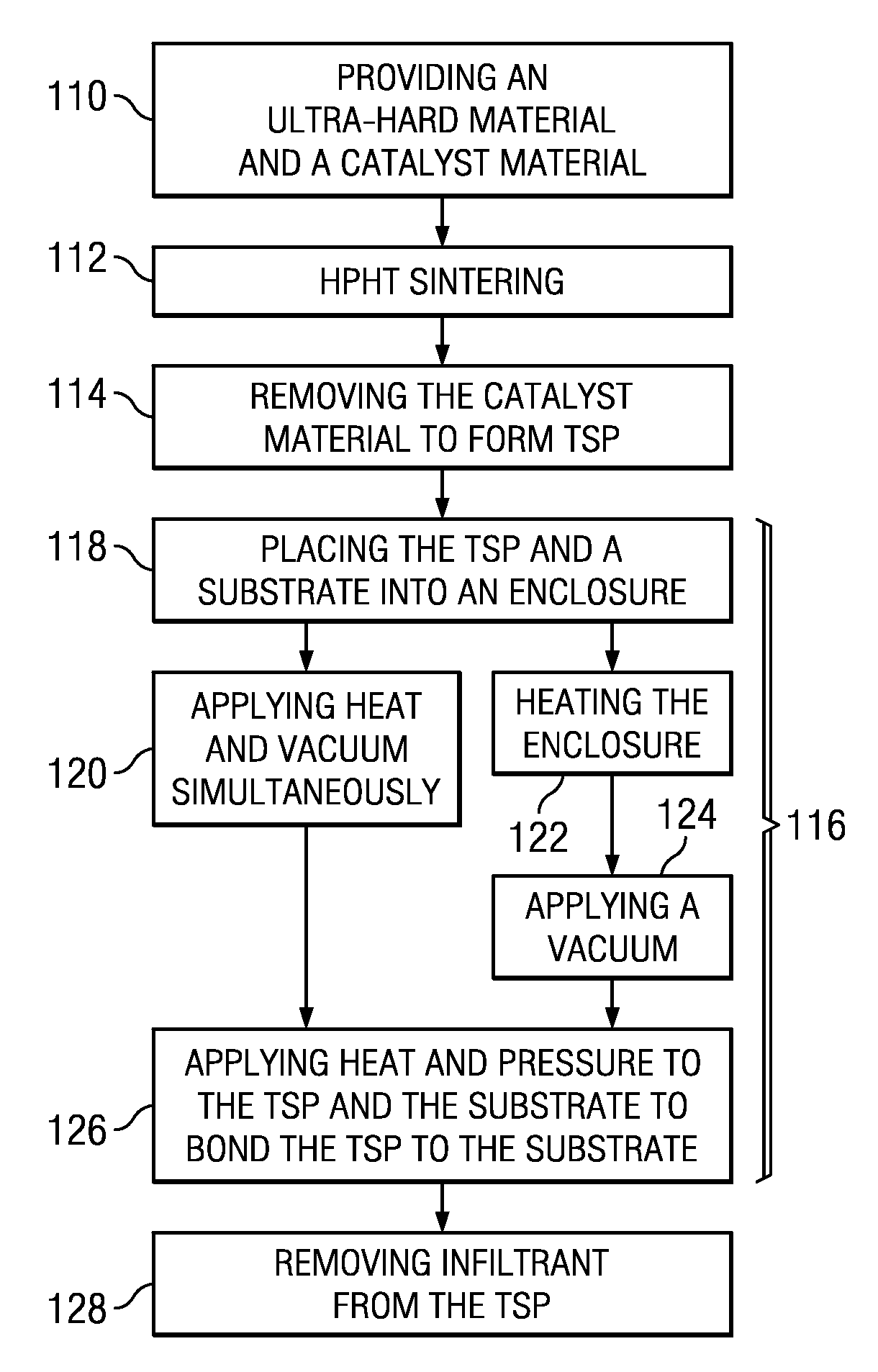
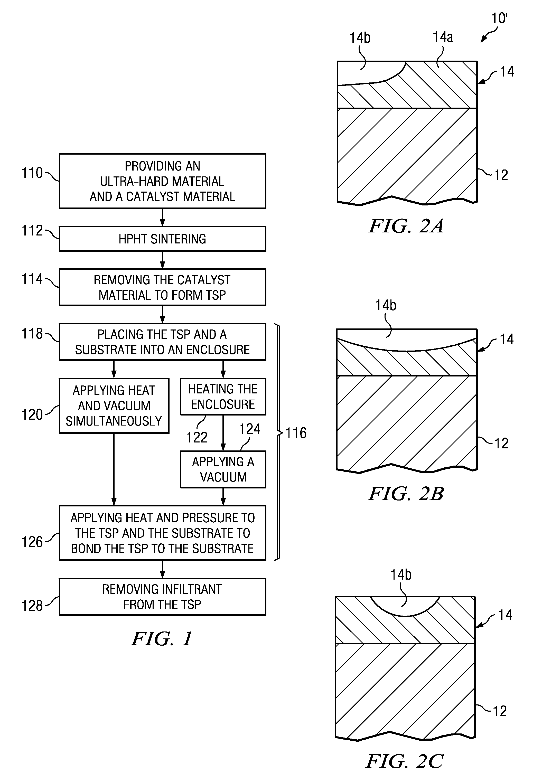
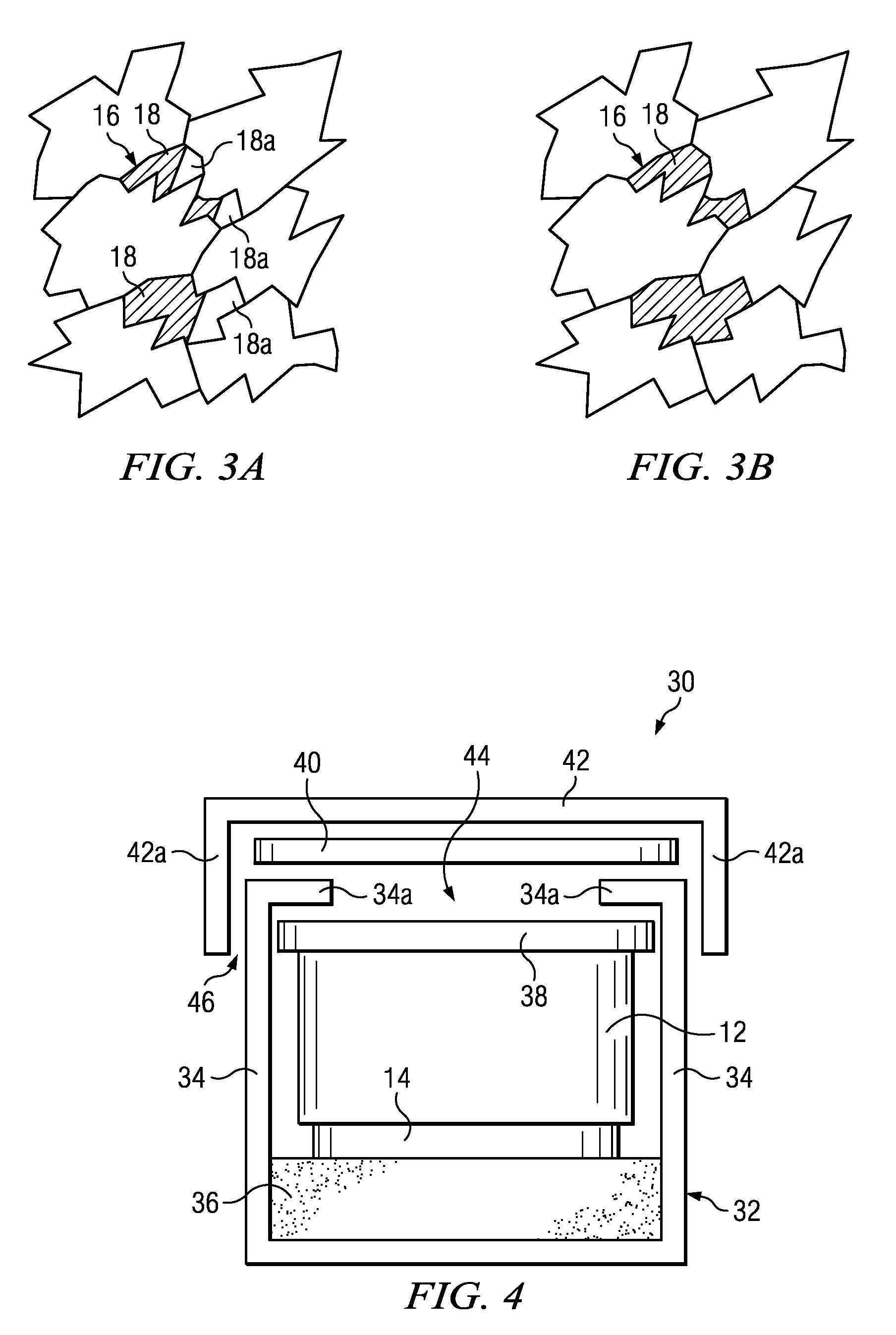
[0023]The present invention involves the use of a vacuum-sealed enclosure during a bonding process to improve the properties of an infiltrated TSP cutting element. In one exemplary embodiment, diamond crystals and a catalyst material are high-pressure high-temperature sintered to form a polycrystalline diamond material (PCD). If a substrate is present during this sintering step, catalyst material from the substrate infiltrates the diamond crystal layer. After sintering, the substrate is removed. The catalyst is removed from the PCD, forming a thermally stable product (TSP). In this leaching or removal process, substantially all (about 95% or more, for example 98% or more, or even 99% or more) of the catalyst is removed from at least a portion of the PCD, forming TSP. Alternatively, leaching can be done prior to removing the substrate from the PCD. The TSP is then bonded to a substrate via an HPHT bonding process. The TSP material and the substrate are placed into an enclosure such a...


PUM

PropertyMeasurementUnit
temperatureaaaaaaaaaa
pressureaaaaaaaaaa

Abstract

In one aspect, a vacuum-sealed can is used during the bonding process to improve the properties of an infiltrated TSP cutting element. In one embodiment, ultra hard diamond crystals and a catalyst material are sintered to form a polycrystalline diamond material (PCD). This PCD material is leached to remove the catalyst, forming a thermally stable product (TSP). The TSP material and a substrate are placed into an enclosure such as a can assembly, heated, and subjected to a vacuum in order to remove gas, moisture and other residuals that can inhibit infiltration of the infiltrant into the TSP layer. The can assembly is then subjected to high temperature, high pressure bonding to bond the TSP material to the substrate. During bonding, material from the substrate infiltrates the TSP layer.

Description

CROSS-REFERENCE TO RELATED APPLICATIONS:[0001]This application claims priority to U.S. Provisional Application No. 61 / 232,228, filed Aug. 7, 2009, which is hereby incorporated by reference in its entirety.BACKGROUND OF THE INVENTION[0002]Cutting elements, such as shear cutter type cutting elements used in rock bits or other cutting tools, typically have a body (i.e., a substrate) and an ultra hard material. The ultra hard material forms the cutting surface of the cutting element, and the substrate is typically provided for the purpose of attaching the ultra hard material to the cutting tool. The substrate is generally made from tungsten carbide-cobalt (sometimes referred to simply as “cemented tungsten carbide,”“tungsten carbide” or “carbide”). The ultra hard material layer is a polycrystalline ultra hard material, such as polycrystalline diamond (“PCD”), polycrystalline cubic boron nitride (“PCBN”) or thermally stable product (“TSP”) such as thermally stable polycrystalline diamond...

Claims


Application Information

Patent Timeline
Patent Type & Authority Applications(United States)
IPC IPC(8): C09K3/14
CPCB22F7/062B24D18/0009C01B31/06C22C26/00C22C2204/00B22F2998/10B24D3/10B01J2203/0685B01J2203/0655B01J2203/062B01J3/062B22F2003/244B22F3/1208B22F3/15
Inventor CARIVEAU, PETER T.EYRE, RONALD K.FANG, YI
Owner SMITH INT INC
Why Eureka
Try Eureka