Electromagnetic wave oscillating devices

Active Publication Date: 2011-02-10
NGK INSULATORS LTD
View PDF8 Cites 10 Cited by
  • Summary
  • Abstract
  • Description
  • Claims
  • Application Information

AI Technical Summary

Benefits of technology

[0014]However, the absorbance of the terahertz wave with a frequency of 0.1 THz to 3 THz is considerable in the oscillating substrate. Most of the oscillated terahertz wave is thus absorbed during the propagation in a short distance and not oscillated to the outside of the oscillating substrate. Therefore, according to “Cherenkov-type phase-matched widely tunable THz-Wave generation using lithium niobate waveguide” (the 56'th Applied Physics Related Association Conference, Proceedings, 2009 spring, Tsukuba University, 30p-P1-3), the thin oscillating substrate is used for reducing the absorbance of the terahertz wave oscillated by parametric effect in the oscillating substrate.
[0015]When the thickness of the oscillating substrate is lowered, however, the mechanical strength of the oscillating substrate becomes considerably low, so that its handling would be difficult. The inventors thus reached the idea of adhering the oscillating substrate onto a separate supporting body. According to such device structure, however, it is proved that the intensity of the terahertz wave oscillated to the outside of the device is further lowered.
[0016]An object of the present invention is, in a device of oscillating an electromagnetic wave having a frequency of 0.1 THz to 3 THz from pump and idler waves by parametric effect, to provide a structure for minimizing the absorbance of the electromagnetic wave within the device.
[0023]According to the present invention, as described above, the oscillating substrate is adhered to the separate supporting body with an adhesive. It is thereby possible to maintain the mechanical strength of the device when the oscillating substrate is made thinner, so that the absorbance of the electromagnetic wave oscillated by parametric effect within the oscillation substrate can be reduced.
[0025]Here, the inventors have confirmed the followings. That is, the electromagnetic wave irradiated towards the back face of the oscillating substrate can be drawn to the outside of the device to considerably improve the output power of the electromagnetic wave oscillated to the outside of the device, by forming a film reflecting the electromagnetic wave on the surface of the supporting body on the side of the adhesive layer. The present invention is based on the discovery.

Problems solved by technology

When the thickness of the oscillating substrate is lowered, however, the mechanical strength of the oscillating substrate becomes considerably low, so that its handling would be difficult.

Method used


Image

  • Electromagnetic wave oscillating devices
  • Electromagnetic wave oscillating devices
  • Electromagnetic wave oscillating devices

Examples


##ventive example 1

Inventive Example 1

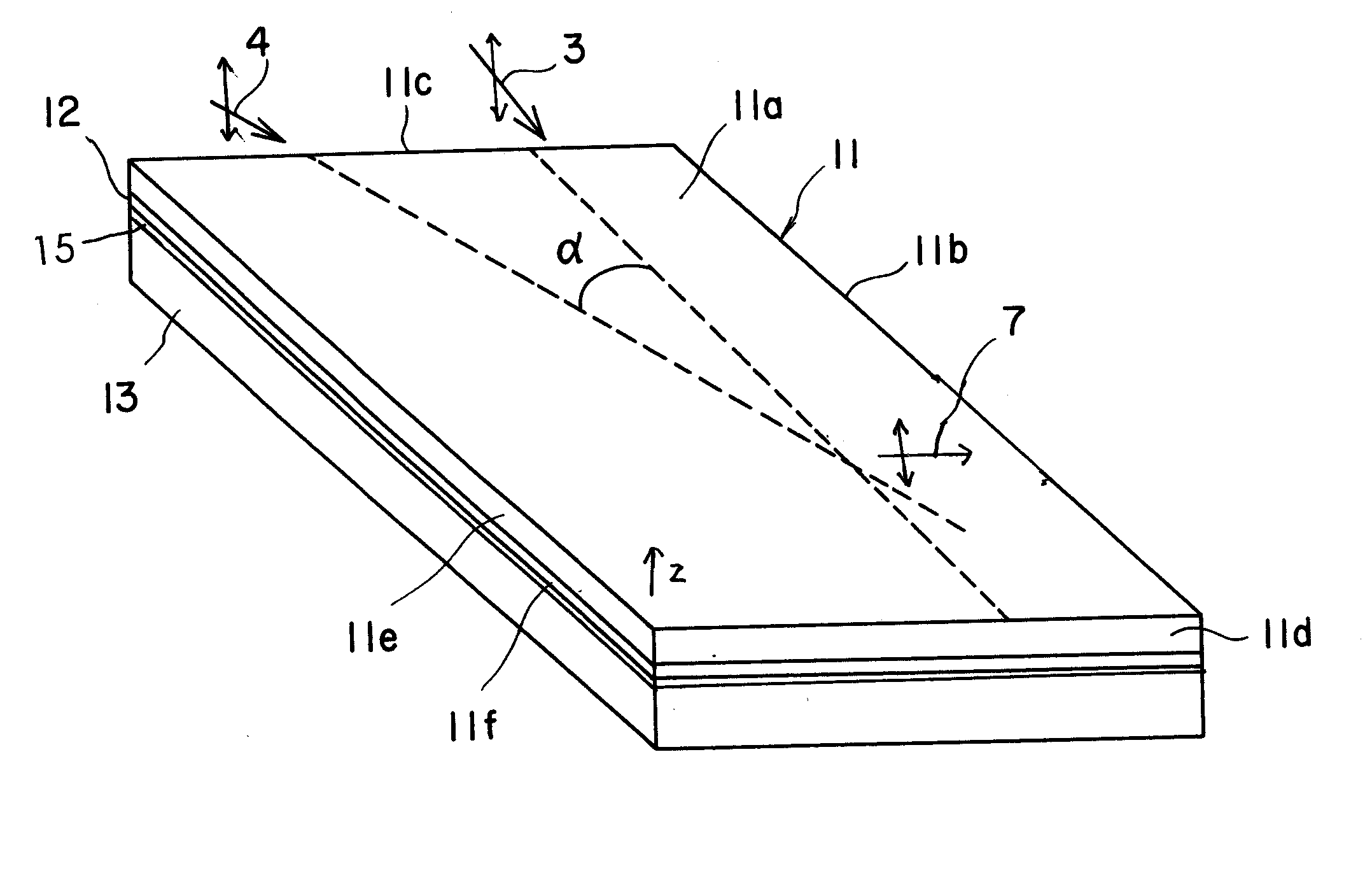
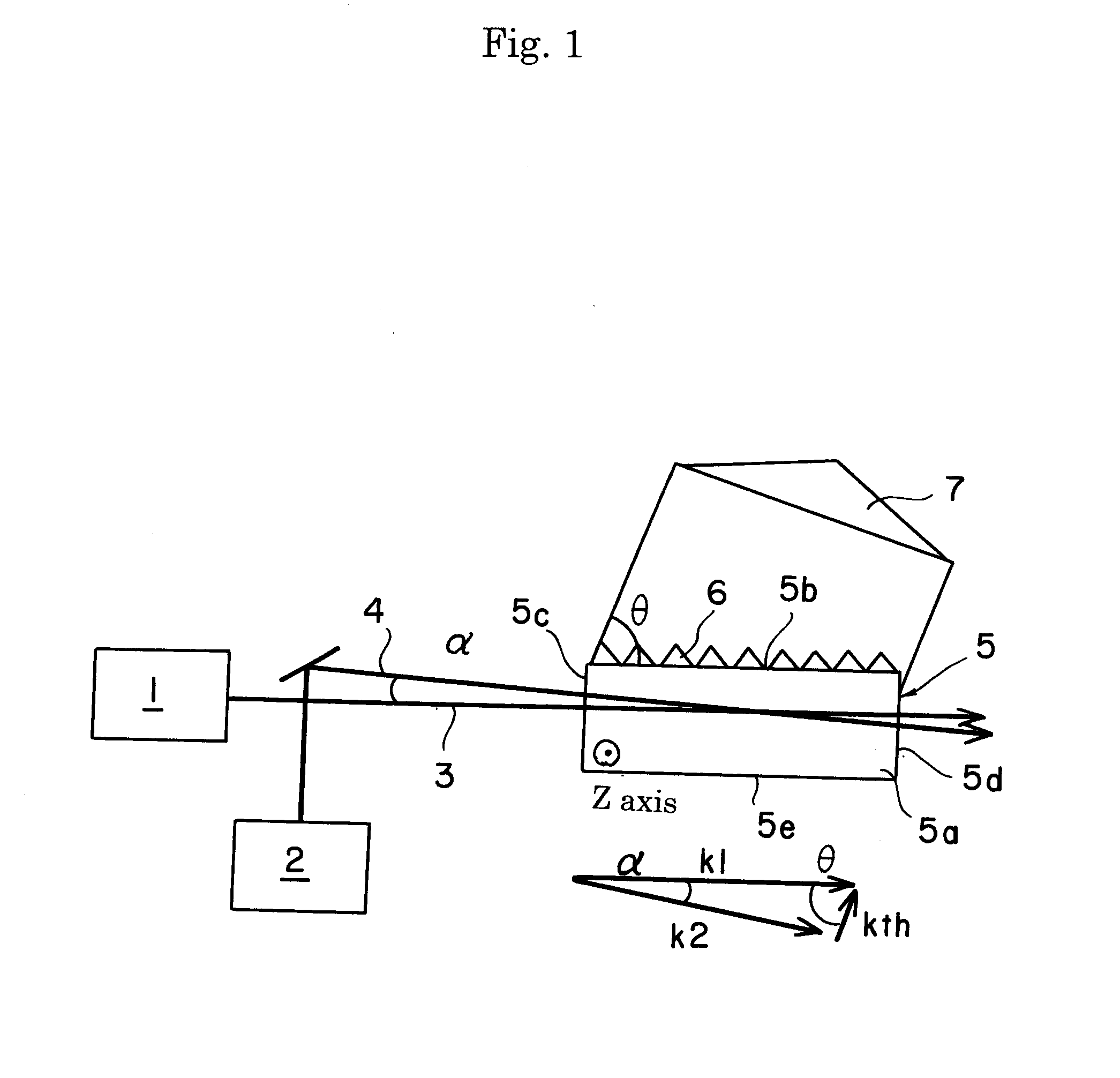
[0075]The terahertz wave oscillating device described referring to FIGS. 3, 4 and 5 (b) was produced.

[0076]Specifically, a z-plate of lithium niobate single crystal was used as the supporting body 13. On the joining surface of the supporting body, titanium, platinum and gold were formed by vapor deposition in thicknesses of 100 angstrom, 200 angstrom and 1 μm, respectively. Then, platinum and titanium were formed in thicknesses of 200 and 100 angstrom, respectively, for further improving the adhesive strength to form the reflective film 15. The reflectivity of the thus formed refractive film was measured by a Fourier Transform Infrared Spectroscopy system (for example, Brucker IFS66v / S) to be more that 90 percent in the terahertz band. The oscillating substrate had a refractive index of 2.14 with respect to the pump wave (wavelength of 1064 nm). An adhesive was applied onto the joining face of the supporting body 13 in a thickness of 1 μm to adhere the z-plate of ...

##ventive example 2

Inventive Example 2

[0082]The terahertz wave oscillating device described referring to FIG. 6 was produced.

[0083]Specifically, a y-plate of lithium niobate single crystal was used as the supporting body 13. On the joining surface of the supporting body 13, titanium, platinum and gold were formed by vapor deposition in thicknesses of 100 angstrom, 200 angstrom and 1 μm, respectively. Then, platinum and titanium were formed in thicknesses of 200 and 100 angstrom, respectively, for further improving the adhesive strength to form the reflective film 15. The reflectivity of the thus formed refractive film was measured by a Fourier Transform Infrared Spectroscopy system (for example, Brucker IFS66v / S) to be more that 90 percent in the terahertz band. The oscillating substrate had a refractive index of 2.14 with respect to the pump wave (wavelength of 1064 nm). An adhesive was applied onto the joining face of the supporting body 13 in a thickness of 1 μm to adhere the y-plate of MgO-doped l...


PUM


Abstract

It is provided a device of oscillating an electromagnetic wave having a frequency of 0.1 THz to 3 THz from pump and idler waves by parametric effect. The device includes a supporting body 13, an oscillating substrate 11 of a non-linear optical crystal, an adhesive layer 12 adhering the supporting body 13 and oscillating substrate 11, and a film 15 reflecting the electromagnetic wave formed on a surface of the supporting body 13 on the side of the adhesive layer 12. The oscillating substrate 11 has an upper face, a bottom face and an incident face on which the pump wave is made incident. The adhesive layer 12 has a refractive index with respect to the pump wave lower than that of the oscillating substrate 13.

Description

[0001]This application claims the benefit of Japanese Patent Application P2009-185768 filed on Aug. 10, 2009, the entirety of which is incorporated by reference.TECHNICAL FIELD[0002]The present invention relates to a device of oscillating so-called terahertz wave.BACKGROUND ARTS[0003]Terahertz waves are electromagnetic waves generally having a frequency of 0.1 THz to 10 THz, and are expected for basic fields such as physical properties, electrospectroscopy, bioscience, chemistry and pharmaceutical science and for applied fields of atmospheric environmental assessment, security, material test, food test and communication.[0004]As a device for oscillating terahertz waves, it has been developed a backward wave oscillator (BOW) and photomixing in several hundreds GHz band and free electron energy laser, p-Ge laser and quantum cascade laser (QCL) for 1 THz or more. These devices, however, have problems in the miniaturization and improvement of output power.[0005]On the other hand, it has...

Claims


Application Information

Patent Timeline
IPC IPC(8): G02F1/39G02F1/355
CPCG02F2203/13G02F1/39
Inventor KONDO, JUNGOAOKI, KENJIIWATA, YUICHIEJIRI, TETSUYA
Owner NGK INSULATORS LTD
Why Eureka
Try Eureka