Method of determining impact severity and adaptive impact attenuation

a technology of impact severity and impact attenuation, applied in the direction of shock absorbers, pedestrian/occupant safety arrangements, instruments, etc., can solve the problems of low-amplitude shock and vibration, the vehicle cannot automatically adapt its energy absorption as a function of payload weight or as a function of real-time environmental measurements, and the vibration is little to no. , to achieve the effect of minimizing the shock induced load experienced, preventing vehicle occupant injury, and efficiently reducing the shock impuls

Active Publication Date: 2011-02-10
INNOVITAL LLC
View PDF4 Cites 68 Cited by
  • Summary
  • Abstract
  • Description
  • Claims
  • Application Information

AI Technical Summary

Benefits of technology

[0011]It is an object of the present invention to prevent vehicle occupant injury and / or protect critical electronic / devices during shock events.
[0012]It is another object of the present invention to minimize the shock induced load experienced by the occupant / payload by utilizing the full or desired stroke of the energy absorption system.
[0013]It is another object of the present invention to provide a control signal to an energy absorber in conjunction with an energy absorption system to cause the absorber to apply the necessary oppositional force.
[0014]Accordingly, there is provided a novel system and process for determining the severity of an impact and for controlling an adaptive energy absorption system thereto. The method utilizes an a priori estimate of impact acceleration pulse characteristics (magnitude, duration, shape, etc.) and payload information (mass) in combination with measured dynamic motion information. Given the a priori estimate of impact acceleration pulse characteristics and measured dynamic motion information, the present invention determines peak amplitude and duration of the anticipated shock event, and uses this to determine the required constant oppositional control force to apply to efficiently mitigate the shock impulse to the payload. Sensor(s) monitor in real time the vehicle and / or payload velocity in anticipation of a shock event. A controller automatically detects a shock event and, based on the a priori information, estimates the entire shock impulse curve and duration. The controller then calculates a desired oppositional force and adjusts an energy absorber to apply the appropriate amount of force in real-time throughout the shock event to more efficiently mitigate shock and avoid damage to a payload and / or injury to an occupant.

Problems solved by technology

Severe shock events may include harsh vertical or crash landings of aircraft, severe water impacts of high speed watercraft, and harsh ground impacts of ground vehicles, or even horizontal crashes of ground vehicles.
Moreover, lower amplitude shock and vibration tend to result from normal operation of such vehicles, including aircraft air loads or rotor loads, ground vehicles traversing rough terrain, etc.
Most existing protection systems employ energy absorbers (EAs) as opposed to springs or other energy storage devices because the latter are prone to inflicting harmful force as they recoil or rebound.
However, FPEAs are passive, meaning that they cannot automatically adapt their energy absorption as a function of payload weight or as a function of real-time environmental measurements such as shock level, impact velocity, vibration levels, etc.
Because of this, these systems provide little to no isolation of vibration.
One key challenge in controlling an electronically adjustable energy absorption system is determining how to adapt the force levels to effectively minimize the loads transmitted to the payload for each individual impact.
If an adaptive energy absorption system only reacts to a measured impact pulse, the system may exhaust a considerable amount of its limited stroke capability before it is able to make any force adjustments.
This wasted stroke will either necessitate additional stroking capability (which in turn requires larger energy absorbers and so may not be geometrically possible for a given application), or else risk the system reaching end-stop impact (which could be harmful to the payload).
Consequently, utilizing more stroke than necessary in a spring-return adaptive suspension system is not ideal because it can result in more force being transmitted to the payload.

Method used


Image

  • Method of determining impact severity and adaptive impact attenuation
  • Method of determining impact severity and adaptive impact attenuation
  • Method of determining impact severity and adaptive impact attenuation

Examples


Embodiment Construction

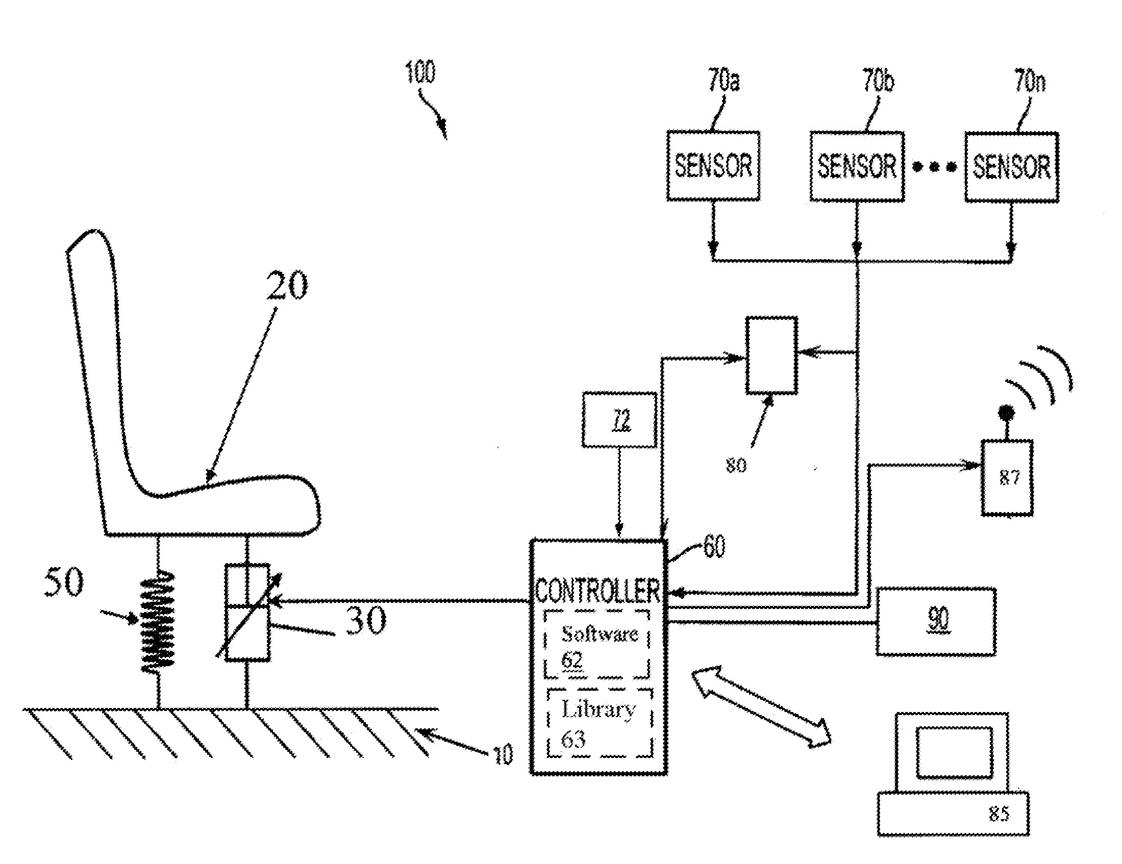
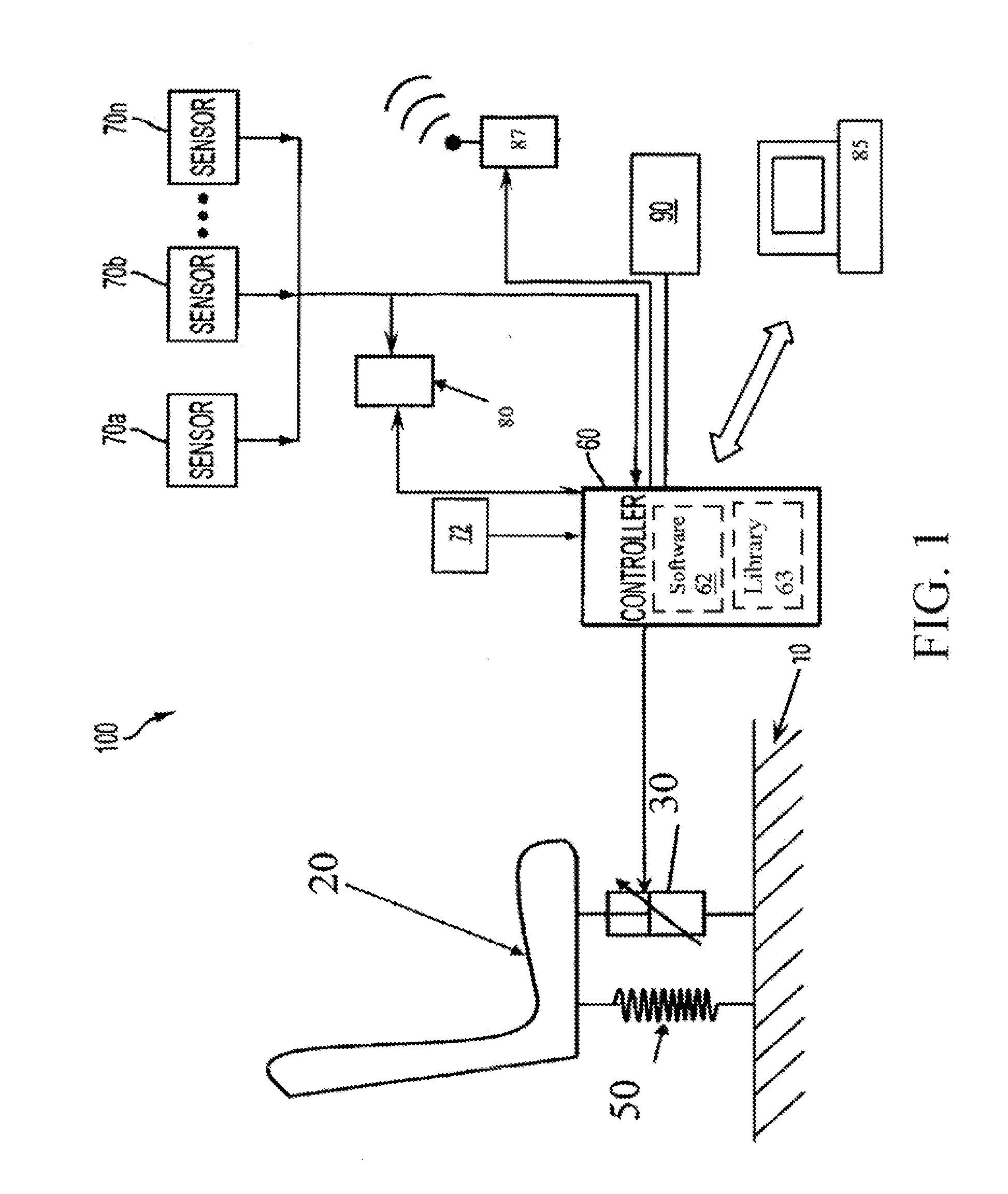
[0018]The control system according to the present invention will be herein shown in the context of a shock energy absorption system for a vehicle seat, although the invention is applicable to any payload shock energy minimization application. In the vehicle seat context, the control system includes a plurality of vehicle-mounted components, generally including a controller (processor with memory), one or more sensors (displacement, velocity, or accelerometer) connected to the processor for monitoring impact velocity in real time, and a VPEA operatively connected between the vehicle seat and vehicle frame.

[0019]FIG. 1 is an exemplary illustration of a suitable adaptive energy absorption system 100 for a vehicle seat, according to an embodiment of the invention. The seat 20 may be any type of vehicle seat including, but not limited to, aircraft (e.g., rotorcraft, fixed wing, etc.) seats, land vehicle seats (e.g., seats for heavy-duty military, agricultural, and construction vehicles, ...


PUM


Abstract

An adaptive energy absorption system for a vehicle seat is disclosed, utilizing an adaptive energy absorber or variable profile energy absorber (VPEA) for mitigating occupant injury due to extreme vehicle movement (e.g., during a vehicle shock event), and/or for mitigating vibration experienced by an occupant of the vehicle seat during normal vehicle operating conditions. The adaptive energy absorption system achieves the aforementioned objectives for a wide range of occupant weights and load levels. An alternate configuration of a dual-goal energy absorption system is also disclosed that enables both shock mitigation and vibration isolation.

Description

CROSS-REFERENCE TO RELATED APPLICATION(S)[0001]The present application is a continuation-in-part of U.S. application Ser. No. 11 / 670,773 filed Feb. 2, 2007.BACKGROUND OF THE INVENTION[0002]1. Field of the Invention[0003]The present invention relates generally to energy absorbers and energy absorption systems, and more particularly, to adaptive energy attenuation systems for impact events, and control thereof.[0004]2. Description of the Background[0005]The primary function of a shock and vibration protection system is to minimize the potential for equipment damage and / or personnel injury during shock and vibration loading. Such systems are important for vehicular applications, including aircraft, ground vehicles, marine vehicles, etc. Severe shock events may include harsh vertical or crash landings of aircraft, severe water impacts of high speed watercraft, and harsh ground impacts of ground vehicles, or even horizontal crashes of ground vehicles. Moreover, lower amplitude shock and ...

Claims


Application Information

Patent Timeline
Patent Type & Authority Applications(United States)
IPC IPC(8): B60R21/00
CPCB60N2/4242B64D11/0619B60N2/4279B60N2/501B60N2/522B60R21/0132B60R21/0136B60R21/055B60R2021/01252B64D11/0689F16F15/002F16F15/02F16F2222/06F16F2224/043F16F2224/045B60N2/42736B60R21/01332
Inventor HIEMENZ, GREGORYHU, WEIVORA, VAIBHAV
Owner INNOVITAL LLC
Why Eureka
Try Eureka