
Integrated Circuit Modeling Method and Framework Tool

a technology of integrated circuits and framework tools, applied in cad circuit design, program control, instruments, etc., can solve problems such as human error risk in the same time, and achieve the effects of minimizing redundant code, improving planning and ease of use, and maximum flexibility and accuracy in the development process

Active Publication Date: 2011-02-17
HONG KONG APPLIED SCI & TECH RES INST CO LTD A LIMITED LIABILITY
View PDF8 Cites 33 Cited by
  • Summary
  • Abstract
  • Description
  • Claims
  • Application Information

AI Technical Summary

Benefits of technology

[0005]It is a further object of the claimed invention to provide improved planning and ease of use in IC design and verification. The claimed invention provides a top-down planning structure, moving from a system definition and high level software language coding, through to optional hardware level synthesis.
[0006]It is a further object of the claimed invention to provide the maximum flexibility and accuracy in the development process, particularly during verification. The improved modeling method according to the claimed invention enables true co-simulation of modules coded in high level software languages and hardware description languages (also referred to herein as a register transfer level “RTL” language), such as SystemC and Verilog respectively. “Coding language” refers to either one or both of high level software language and hardware description language. The instantiation of which modules (high level or hardware level) in the co-simulation environment may be user selectable.
[0007]It is a further object of the claimed invention to minimize redundant code and maximize transferability of base code. The claimed invention also has the object of utilizing the same common base code in the architecture exploration, verification and RTL synthesis stages. Preferably this is achieved through establishing a set of functional cores and selectively attaching or providing appropriate code to the appropriate cores at the appropriate stage. The same set of functional cores are preferably coded in a high level language and are deployable at any step of the method by changing or adding the appropriate code as required. The code provides external environment cooperative engagement functionality to the cores, and is attached according to the coding environment in which the core will operate, thus permitting the cores to cooperatively engage with an external environment. Preferably the external environment cooperative engagement functionality is provided by an interchangeable wrapper or inter-module communication wrapper. Preferably the cooperative engagement functionality is automatically generated, for example by an interface generator.
[0008]It is a further object of the claimed invention to minimize man hours and errors, and accelerate one or more steps in the IC development process particularly including the verification step which generally occupies up to 70% of the IC design process. The interface generator of the claimed invention generates the interface code that is provided to the external environment cooperative engagement functionality to facilitate communication across otherwise incompatible interfaces, for example by translation between the interfaces at the transaction level and the register transfer level. The translation may be between abstraction levels and / or between coding languages. The input to the interface generator of the hardware specifications may be in any form, but preferably they do not use any specific input specification language, only knowledge of hardware specifications, thus facilitating user access to the modeling framework tool. Preferably the inputs are one or multi dimensional arrays, and even more preferably are two dimensional arrays such as spreadsheets. The interface generator may generate multiple kinds of wrappers as selected, which may be for different simulators. The interface generator may also have error handling functions and verification of the generated interface code functions. The generator may enable the generated code to be ported to other software platforms.

Problems solved by technology

However, there are challenges in connecting these cores mutually together throughout the development process, and also connecting them with functional elements based on lower level description languages that are used in the design and verification process.
Keeping the interfaces current between high and low level elements as they are updated requires constant manual updates to interface code with concurrent risk of human error.

Method used


Image

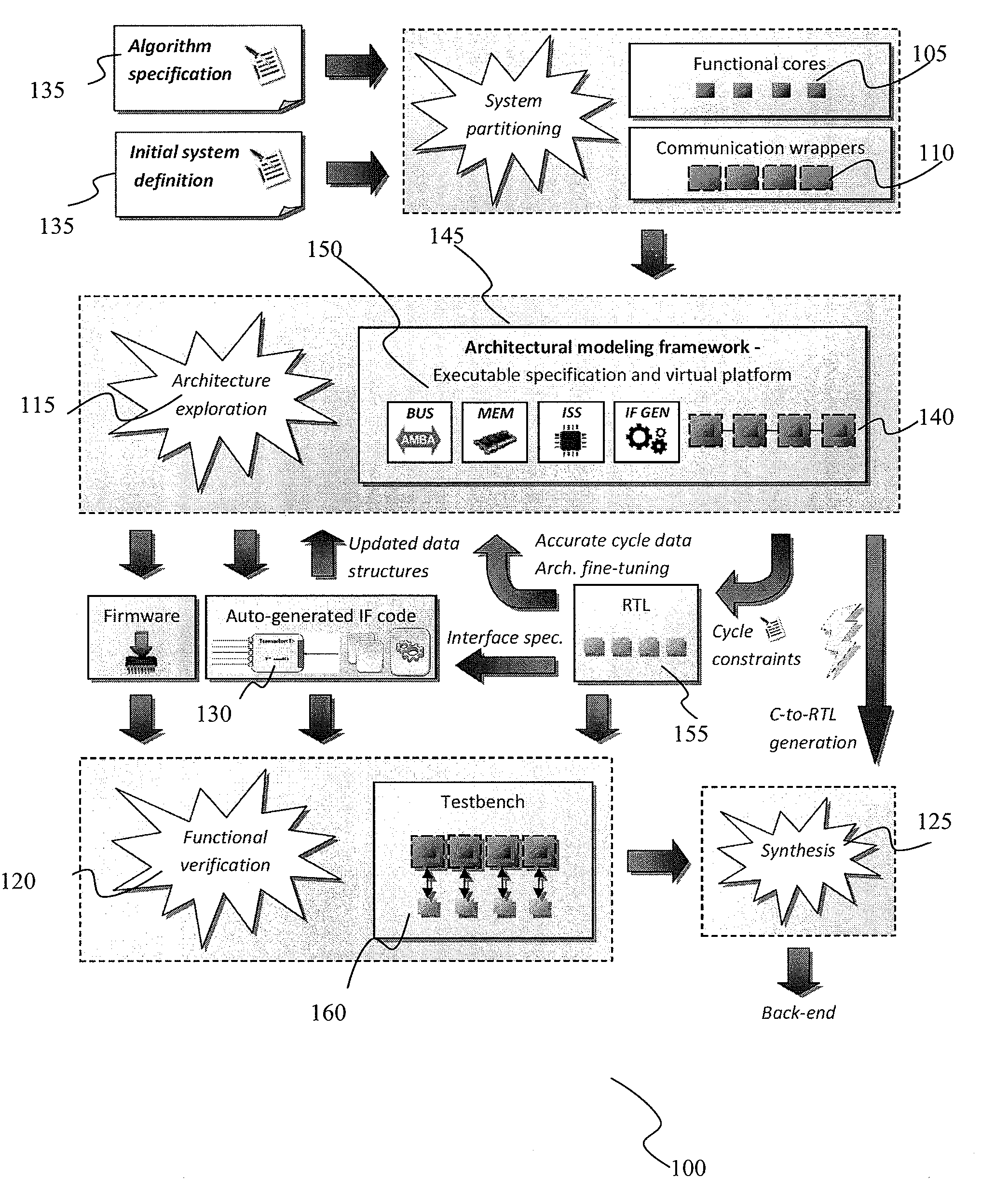
  • Integrated Circuit Modeling Method and Framework Tool
  • Integrated Circuit Modeling Method and Framework Tool
  • Integrated Circuit Modeling Method and Framework Tool

Examples


Embodiment Construction

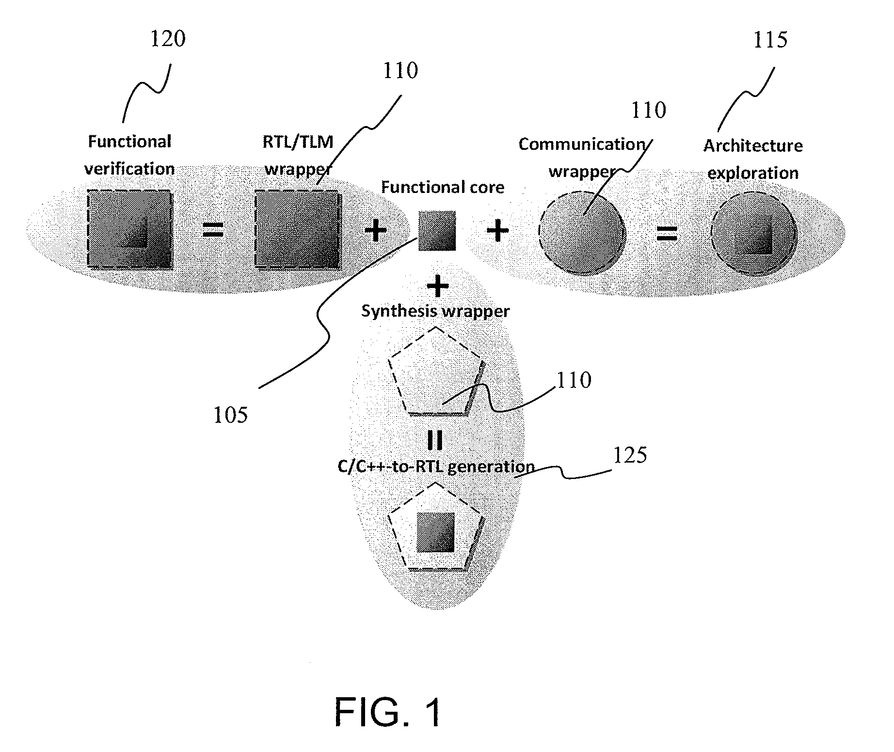
[0022]FIG. 1 exemplifies how different wrappers 110 can be applied to the same functional core 105 and used in different steps of the method 100. For example, by applying RTL / TLM wrapper 110 which is a type of interconversion or co-simulation wrapper enables core 105 to be used in functional verification step 120 whereas application of a communication wrapper 110 allows usage during architecture exploration step 115 whereas application of a synthesis wrapper 110 enables C to RTL generation step 125.

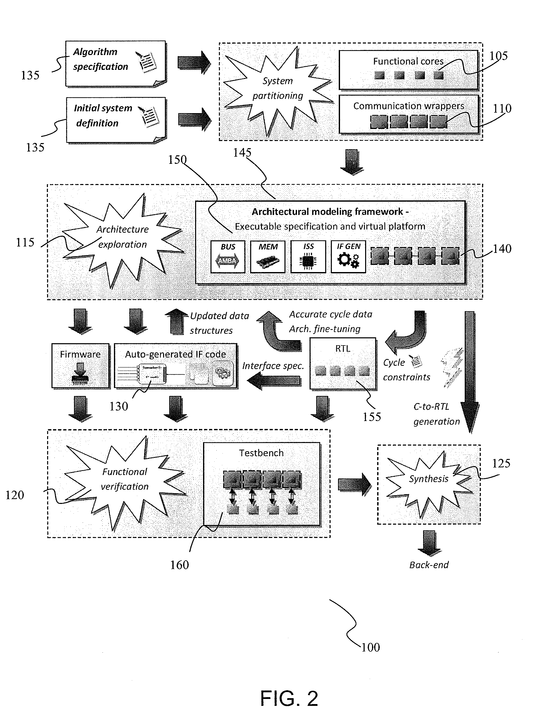
[0023]This maximizes the reuse of functional code contained within each functional core 105 throughout the modeling method 100 (FIG. 2). The wrapper will thus cooperatively engage with an external environment allowing the wrapped code, such as the functional cores 105, to be used in different environments.

[0024]The functional cores and wrappers represent the basic functional blocks of a software model of the integrated circuit, which is defined in system design inputs. As shown in FIG. 2 ...


PUM


Abstract

An integrated circuit modeling method 100 implementable on computer, which has an executable software model 145 having modules 140 of reusable functional cores 105 coded in a high level language and a virtual platform of the integrated circuit employable in an architecture exploration step 115. A modeling library of modules coded in high level languages and hardware level languages are provided and instantiated according to user input in a functional verification step 120 having a co-simulation environment, with interface code 170 between modules automatically generated by an interface generator 130 based on a two dimensional data array of hardware specification inputs 205, the interface code 170 further interfacing with wrappers engaged between high and hardware level language modules.

Description

CROSS-REFERENCE TO RELATED APPLICATIONS[0001]There are no related applications.TECHNICAL FIELD[0002]The claimed invention relates generally to the design and verification of integrated circuits (“IC”). In particular, the claimed invention relates to a computer implementable modeling method of designing, simulating, verifying and implementing an IC. With greater particularity the claimed invention relates to a method of modeling using software models of an IC design at different levels of abstraction, with reuse of a common code base engaged with appropriate translation wrappers and automatic generation of interface code.SUMMARY OF THE INVENTION[0003]The constant increase in complexity of integrated circuits (defined herein to include Systems-On-a-Chip, “SOC”) requires correspondingly greater effort for design and functional verification of the designed circuits prior to actually synthesizing the circuit in silicon. Software models of hardware modules are commonly used for various pu...

Claims


Application Information

Patent Timeline
IPC IPC(8): G06F17/50
CPCG06F2217/86G06F17/5022G06F30/33G06F2117/08
Inventor LI, SUET FEILU, YUNZHAOOLSSON, ERIKSHI, MING HUA
Owner HONG KONG APPLIED SCI & TECH RES INST CO LTD A LIMITED LIABILITY
Learn More