Resonant Inverter With Sleep Circuit

a technology of inverter and circuit, applied in the field of power supplies, can solve the problems of increasing the initial monetary cost of electronic ballast, increasing the cost of increasing the cost manifest, etc., and achieves the effect of increasing the initial monetary cost of electronic ballast, increasing maintenance costs, and increasing costs for electronics including sleep mode circuits

Active Publication Date: 2011-02-24
OSRAM SYLVANIA INC
View PDF3 Cites 16 Cited by
  • Summary
  • Abstract
  • Description
  • Claims
  • Application Information

AI Technical Summary

Benefits of technology

[0006]Conventional techniques for pulsing a sleep mode of an electronic lamp ballast, such as those described above, involve multiple circuit components and configurations. Such large numbers of components used within sleep mode circuits, as well as their complex configurations, result in increased costs for including sleep mode circuits in electronics. These increased costs manifest throughout the development, production, and usage of an electronic ballast. Sleep mode circuits that include a large number of components not only increase the initial monetary cost of electronic ballasts, but also result in more possible failure points throughout the life of the electronic ballast. This may, in turn, lead to increased maintenance costs. In other words, the more components a circuit of an electronic ballast has, the greater the possibility of some component failing, and the longer it takes to find and replace the failed component.

Problems solved by technology

Such large numbers of components used within sleep mode circuits, as well as their complex configurations, result in increased costs for including sleep mode circuits in electronics.
These increased costs manifest throughout the development, production, and usage of an electronic ballast.
Sleep mode circuits that include a large number of components not only increase the initial monetary cost of electronic ballasts, but also result in more possible failure points throughout the life of the electronic ballast.
This may, in turn, lead to increased maintenance costs.
In other words, the more components a circuit of an electronic ballast has, the greater the possibility of some component failing, and the longer it takes to find and replace the failed component.

Method used


Image

  • Resonant Inverter With Sleep Circuit
  • Resonant Inverter With Sleep Circuit
  • Resonant Inverter With Sleep Circuit

Examples


Embodiment Construction

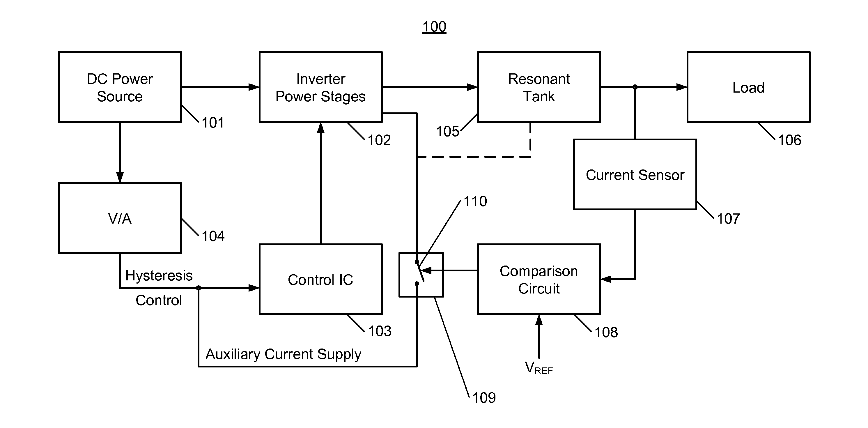
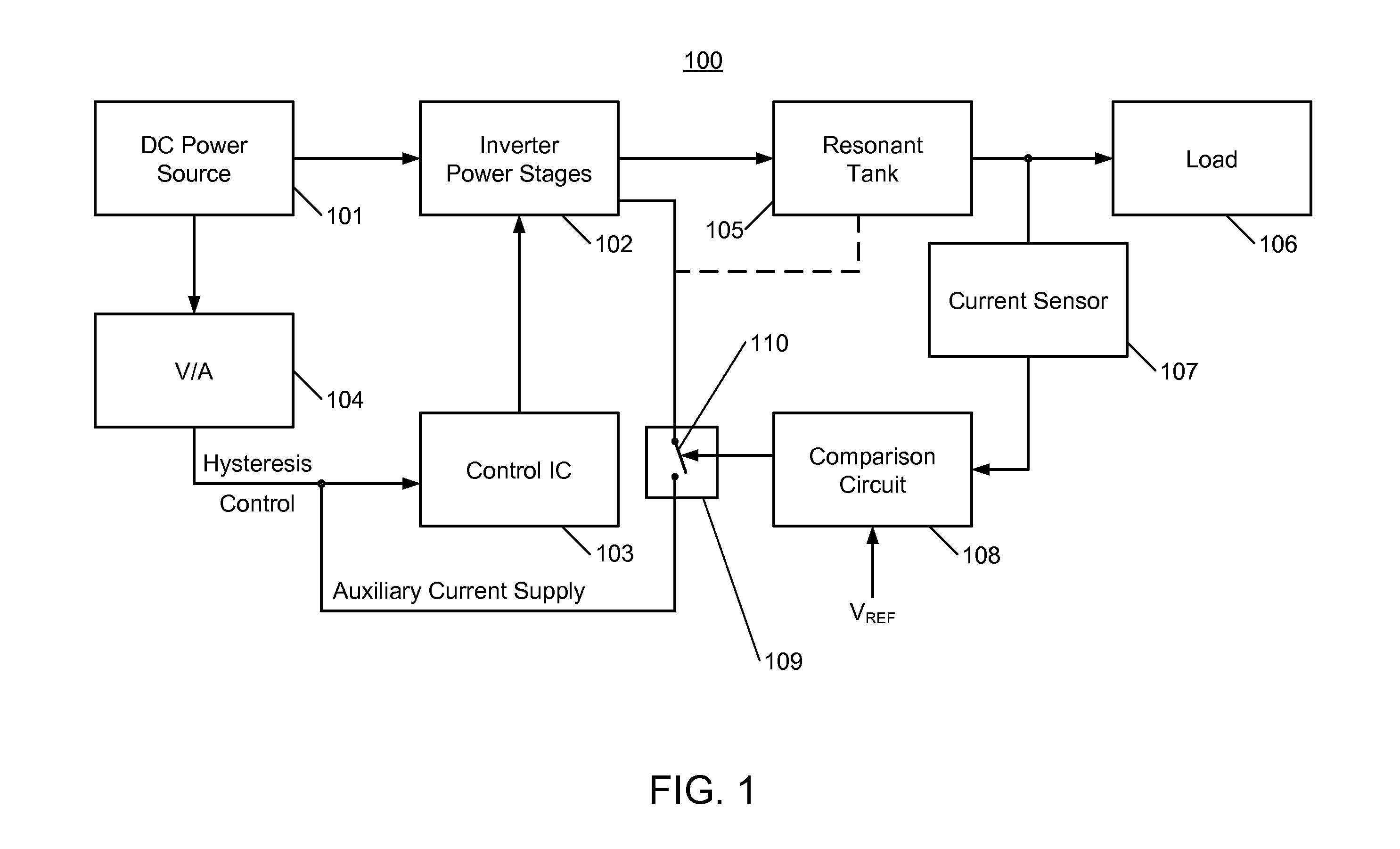
[0018]FIG. 1 shows a block diagram of a resonant inverter 100 including a control IC 103. In some embodiments, the control IC 103 may be referred to herein as a sleep circuit. Alternatively, or additionally, in some embodiments, the sleep circuit may include the control IC 103. A DC power source 1010 powers the resonant inverter 100. In some embodiments, the DC power source 101 may include an AC to DC converter, which is not shown in FIG. 1. In addition to the control IC 103, the resonant inverter 100 includes inverter power stages 102, such as but not limited to a half bridge configured with two FETs (not shown in FIG. 1) that the control IC 103 drives. Current consumption of the control IC 103 in under voltage lockout (UVLO) conditions is considered to be very low, such as but not limited to about 0.2-0.3 mA. The control IC 103 is coupled to the DC power source 101 via a voltage to current converter 104. A storage capacitor, not shown in FIG. 1, is connected between a Vcc pin and ...


PUM


Abstract

A sleep circuit for use in a resonant inverter is disclosed. The sleep circuit activates a “sleep mode” (non-continuous operation) when the inverter output has no connected load, or a connected load is non-operative (e.g., fails). The “sleep mode” utilizes hysteresis control via the under voltage lockout protection feature of a control IC of the inverter. A primary DC source permanently connects to the Vcc pin of the control IC for startup (on) and burst (non-continuous) operation modes. An auxiliary DC source connects to the Vcc pin via a switch for continuous operation mode. A load current sensor controls the switch. When a sensed output current is above a threshold level, the switch connects the auxiliary DC source, and the control IC (and the inverter) operates continuously. When the sensed output current falls below the threshold, the auxiliary DC source is not provided and the inverter operates in “sleep mode”.

Description

CROSS-REFERENCE TO RELATED APPLICATION[0001]The present application claims priority of U.S. Provisional Patent Application Ser. No. 61 / 235,724, filed Aug. 21, 2009, the entire contents of which are hereby incorporated by reference.TECHNICAL FIELD[0002]The present invention relates to power supplies, and more specifically, to power supplies used to operate lamps.BACKGROUND[0003]A typical gas discharge lamp utilizes an electronic ballast to convert AC line voltage to a high frequency current capable of powering the gas discharge lamp. The main component of such an electronic ballast is a resonant DC / AC inverter, which is typically a series resonant DC / AC inverter driven by a control integrated circuit (IC) chip.[0004]A single electronic ballast may power a plurality of lamps placed in a fixture including the electronic ballast. When replacing one or more lamps, or when one or more lamps are damaged, the resonant DC / AC inverter of the electronic ballast should operate without a load be...

Claims


Application Information

Patent Timeline
Patent Type & Authority Applications(United States)
IPC IPC(8): H05B41/16H02M7/48
CPCH02M7/538H02M2001/0032Y02B70/1441Y02B20/186H05B41/2828H05B41/3921Y02B70/16Y02B20/00Y02B70/10H02M1/0032
Inventor ALEXANDROV, FELIX I.
Owner OSRAM SYLVANIA INC
Why Eureka
Try Eureka