
Method and device for processing recorded image information from a vehicle

a technology for recording image information and vehicle, which is applied in the direction of vehicle cleaning, television systems, instruments, etc., can solve the problems of no longer being able to recognize center lines, unable to achieve any improvement in driver assistance function, and unable to achieve the effect of improving driver assistance function

Inactive Publication Date: 2011-02-24
ROBERT BOSCH GMBH
View PDF10 Cites 86 Cited by
  • Summary
  • Abstract
  • Description
  • Claims
  • Application Information

AI Technical Summary

Benefits of technology

The exemplary embodiments and / or exemplary methods of the present invention provides a method for improving the driver assistance function, in particular for driver assistance systems that are based on video images recorded from a vehicle. Through weighting, or even by selecting individual video images or areas of individual images, the image data available for the driver assistance function are subdivided into image data of better or poorer quality.
When the image data are evaluated by the driver assistance system to generate the driver assistance signals, the areas having better-quality image data are weighted more heavily than the image areas having poorer-quality image data. The algorithm utilized in the driver assistance system for evaluating the images determines the best type of weighting for the images or image areas of different quality, which may be applied in principle at two places in the algorithm. Images or image areas of differing quality may enter into the algorithm for analysis together with a number that corresponds to a weighting, or the images are evaluated first by the algorithm without weighting information and the result of the analysis using a chosen algorithm is weighted with the aid of the information about the quality of the particular analyzed image itself. Finally, it is also possible to use both methods side-by-side for the weighting. Weighting, which is explained below in greater detail, makes it possible to perform the recognition of road signs or the recognition of center lines with greater reliability, because the driver assistance signals are influenced to a greater degree by higher-quality images and only to a lesser degree by lower-quality images.
When recording consecutive images, it is possible to improve the weighting of the image data by synchronizing the timing of recording the images with the motion of the windshield wiper. To this end, advantageous use is made of a PLL method, a software-implemented phase locked loop (PLL), which synchronizes a phase counter and the result of the positive wiper detection with each other. Especially in vehicles that are unable to supply exact information about the wiper position, this method is suitable for supplying information about the phase status of the windshield wiper relative to the image recording in a wiper cycle to the algorithm for image evaluation simultaneously with the individual images from the video sensor. For a sequence of many images that extend in time over a plurality of windshield wiper cycles, this results in a temporally periodic weighting of the images as a function of the windshield wiper phase, the images that were recorded in the time immediately after a wiper sweep entering into the image analysis with a higher weighting factor than images that were recorded shortly before a wiper sweep due to the correlation of the phase counter with the wiper frequency.
Synchronization makes it possible to anticipate the passing of the wiper over the recorded image. Because it is known when the next wiper sweep will occur, a high quality measure may be assigned to the first image after the wiper sweep and subsequent images are given a quality rating using a time decay function, so that the image immediately before another wiper sweep is rated the lowest in quality. If it is possible to obtain data from an electrical bus system of the vehicle about whether or not a windshield fan is turned on, it is advantageous not to assign the highest quality rating to the first image after detection of the wiper, but rather to an image reaorded longer after the wiper sweep than the first image. This is because a windshield fan may cause wiper streaks that remain after the wiping to evaporate. Hence the image having the highest quality rating is pushed back in time in relation to the wiper sweep.
In order to improve the quality of evaluation of the image data by the driver assistance system still further, a conventional rain sensor that adjusts the frequency of the windshield wiper may be connected to the system. This signal is used for synchronizing the phase counter, in order to establish a stable phase relationship between the changing windshield wiper frequency after changing rain conditions and the phase counter as quickly as possible. A further effect of the rain sensor coupled with the windshield wiper controller is that the image from the video sensor is not swept by the wiper more frequently than necessary, because in light rain an excessively high frequency of the wiper may result in a large number of low ratings of a recorded image, because the wiper passes through the camera image more frequently than necessary and thereby frequently degrades large image portions unnecessarily.

Problems solved by technology

Since the cameras used for this purpose are mostly located in the upper center of the windshield, or else in specially situated cavities of the vehicle, the cameras do not have access to a better view through the windshield than the driver does.
Consequently, the performance of these systems drops off considerably during rain, because the optical path of the cameras is severely impaired, and therefore center lines can either no longer be recognized at all or only erratically, and road signs cannot be detected at all.
In particular the images of the vehicle's surroundings during rain through the rain-dampened windshield, in some cases severely distorted, enable the above-named driver assistance systems to analyze the recorded image only inadequately or not at all, or raindrops on the windshield act like local lenses and blind the camera so severely that it can no longer record usable images.
An actual improvement of the driver assistance function cannot be achieved by this technique, however.

Method used


Image

  • Method and device for processing recorded image information from a vehicle
  • Method and device for processing recorded image information from a vehicle
  • Method and device for processing recorded image information from a vehicle

Examples


Embodiment Construction

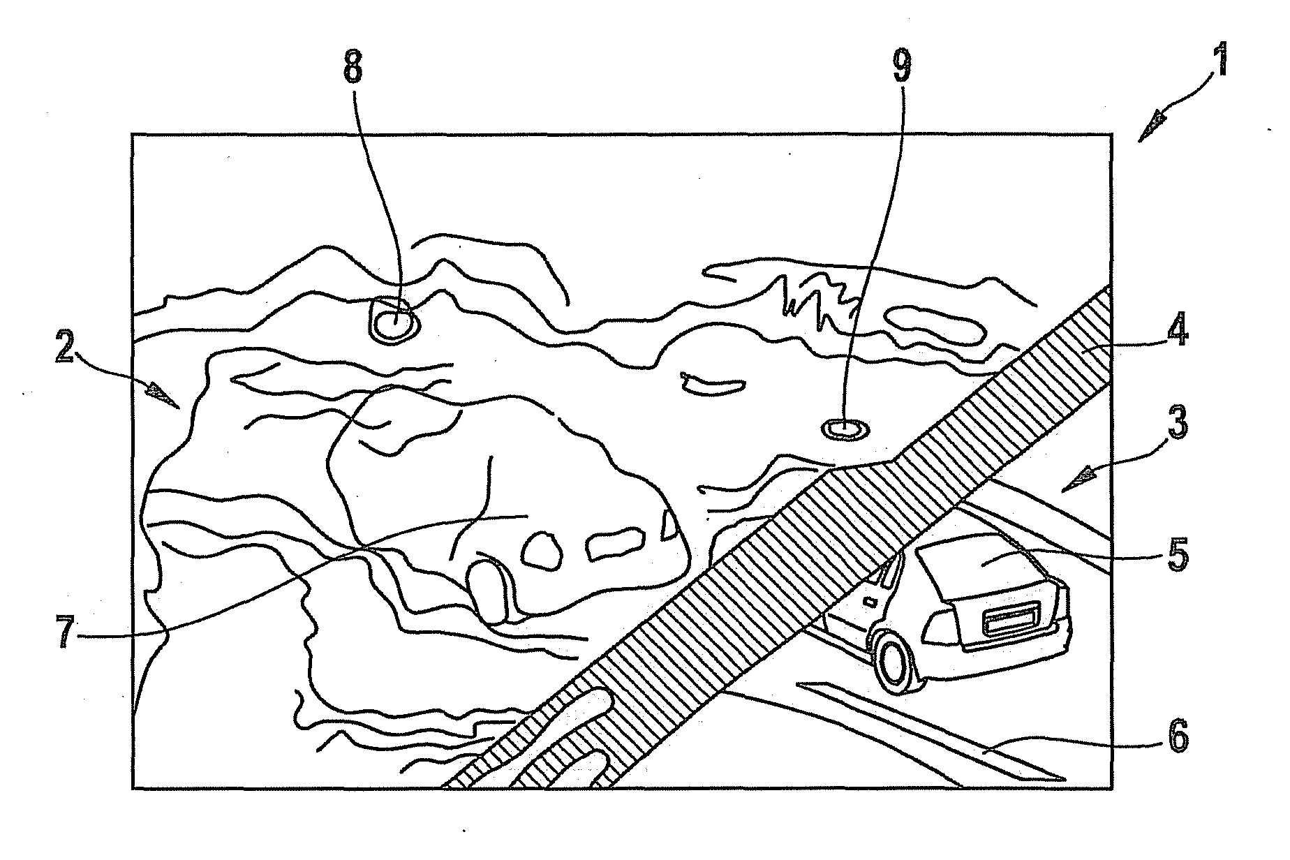
FIG. 1 shows a schematic camera image 1, which is used for a driver assistance system such as RSR, LDW or LKS. Camera image 1 has an image area 2 having very poor quality and an image area 3 having better quality. The two image areas 2 and 3 are separated from each other by a windshield wiper shadow 4, windshield wiper shadow 4 gliding from right to left across image 1. In better-quality image area 3 there are individual image components 5 and 6 present which may be recognized as the rear deck of a vehicle and as a road marking. In poorer-quality image area 2 an image component 7 is likewise visible, which is recognizable only vaguely as the rear deck of another vehicle, because rain on the windshield through which image 1 is recorded distorts the view beyond recognition. In addition to the distortion, short-lived water drops 8 and 9 are present in poorer-quality image area 2, which act like lenses and focus light from preceding vehicles and may blind an exposure control for the cam...


PUM


Abstract

A method for improving the driver assistance function, in particular of driver assistance systems based on video images recorded from a vehicle, and a corresponding device for that purpose made up of a camera and processing unit. To improve the function during rain, the passing of a windshield wiper through the camera image be used to classify individual images and / or portions of images as being of higher or lower quality, in order to improve the quality of the images from the camera. The images from camera are intended to be used for automatic driver assistance systems.

Description

FIELD OF THE INVENTIONThe present invention relates to a method and a device for processing image information recorded from a vehicle.BACKGROUND INFORMATIONImage data of the vehicle's surroundings, supplied by cameras, are required for a great many different driver assistance systems in vehicles. These image data aid in staying in lane (LDW or lane departure warning), to warn the driver for example that he / she is becoming excessively tired; in automatic lane monitoring (LKS or lane keeping support), for example as part of an automatic vehicle steering system; in recognizing traffic signs (RSR, road sign recognition); or with active night vision support with object recognition and warning function. The image data for night vision support are provided by cameras that are capable of night vision.All systems that have a camera-based active recognition function based on image data of the vehicle's surroundings have in common that they are very sensitive to the quality of the available im...

Claims


Application Information

Patent Timeline
IPC IPC(8): H04N7/18
CPCG06K9/00791B60S1/08G06V20/56
Inventor HAUG, KARSTEN
Owner ROBERT BOSCH GMBH
Features
  • Generate Ideas
  • Intellectual Property
  • Life Sciences
  • Materials
  • Tech Scout
  • Unparalleled Data Quality
  • Higher Quality Content
  • 60% Fewer Hallucinations
Learn More