Hydraulic control apparatus

a control apparatus and hydraulic technology, applied in the direction of positive displacement liquid engines, instruments, etc., can solve the problems of power loss and vibration during the engagement of the lockup clutch, and achieve the effect of improving the responsiveness of the clutch control mechanism

Active Publication Date: 2011-02-24
TOYOTA JIDOSHA KK
View PDF0 Cites 23 Cited by
  • Summary
  • Abstract
  • Description
  • Claims
  • Application Information

AI Technical Summary

Benefits of technology

[0006]The invention has been designed in consideration of the circumstances described above, and the invention provides a hydraulic control apparatus capable of improving the responsiveness of a clutch control mechanism for controlling transmission torque of a clutch.
[0008]According to the hydraulic control apparatus described above, it is possible to switch selectively between control in which thermal energy is applied to the oil supplied to the control oil pressure generation apparatus, thereby increasing the temperature of the oil, and control in which thermal energy is not applied to the oil. Therefore, when the control oil pressure is generated by the control oil pressure generation apparatus and used to control activation of the clutch control mechanism, the responsiveness of the control oil pressure can be improved such that the clutch control mechanism can be activated smoothly. Hence, vibration caused by an increase in the transmission torque of the clutch can be suppressed at a relatively early stage.
[0016]According to the hydraulic control apparatus described above, the oil that is ejected from the pump is supplied to the fluid transmission apparatus, and a portion of the warmed oil in the casing of the fluid transmission apparatus is returned to the suction port of the pump through the oil passage and the return oil passage. Thus, the oil that is ejected from the oil pump can be warmed.
[0018]According to the hydraulic control apparatus described above, the oil temperature of the oil ejected from the ejection port of the oil pump is measured, and when the measured oil temperature is equal to or below the predetermined reference oil temperature, a portion of the oil in the oil passage can be returned to the suction port through the return oil passage. Hence, the oil that is ejected from the oil pump can be warmed reliably.
[0024]According to the hydraulic control apparatus described above, the heating wire generates heat when energized, and applies the resulting thermal energy to the oil that is supplied to the control oil pressure generation apparatus. Hence, the oil that is supplied to the control oil pressure generation apparatus can be warmed reliably.

Problems solved by technology

When the lockup clutch is not engaged, slippage occurs in the fluid transmission apparatus, leading to power loss.
However, if the operating responsiveness of a switching valve for engaging and disengaging the lockup clutch is relatively low, vibration may occur during engagement of the lockup clutch even if working oil supplied to a hydraulic chamber for controlling the engagement of the lockup clutch is warmed.

Method used


Image

  • Hydraulic control apparatus
  • Hydraulic control apparatus
  • Hydraulic control apparatus

Examples


first embodiment

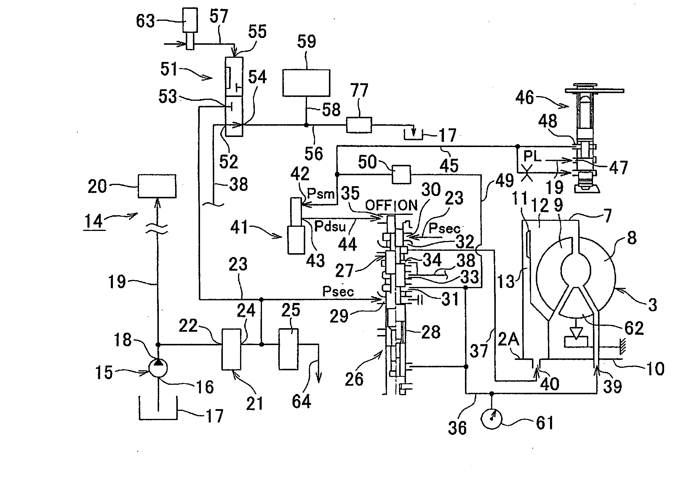
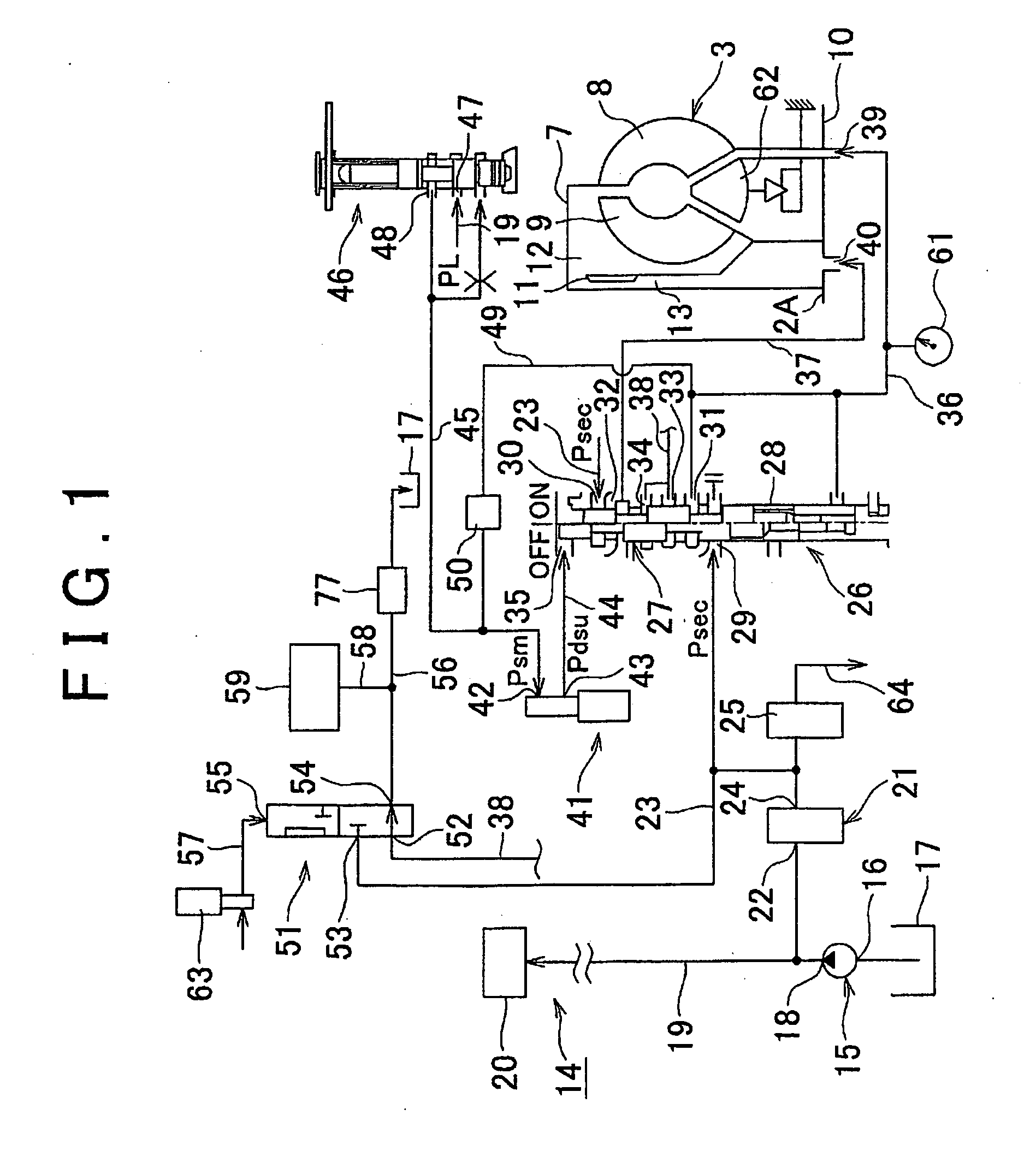
[0045]Next, the interior of the torque converter 3, or more specifically a hydraulic control apparatus 14 for supplying working oil to the interior of the casing 7, will be described with reference to FIG. 1. An oil pump 15 for supplying oil to the hydraulic control apparatus 14 is provided. The oil pump 15 is driven by the engine 2 or a motor (not shown), and any rotating or reciprocating oil pump, for example a gear pump, a vane pump, a plunger pump, or a piston pump, may be used as the oil pump 15. A suction port 16 of the oil pump 15 is connected to an oil pan 17. Oil is stored in the oil pan 17. Further, an oil passage 19 is connected to an ejection port 18 of the oil pump 15.

[0046]Pressurized oil ejected into the oil passage 19 is supplied to a pressurized oil requiring portion 20. The pressurized oil requiring portion 20 includes a hydraulic chamber of a hydraulic actuator for controlling a gear ratio of the transmission 4. A pressure control valve (primary regulator valve) 2...

third embodiment

[0074]Hence, in the third embodiment, if a negative determination is made in step S1, an affirmative determination is made in step S3, and an affirmative determination is made in step S4, the warming control is executed preferentially, and if an affirmative determination is made in step S1 or a negative determination is made in step S3 thereafter, engagement of the lockup clutch 11 is permitted. As a result, the warming control may be executed more reliably. Further, if the control shown in FIG. 7 is executed, an operation defect in the temperature sensitive valve 50 may be determined. Note that the signal from the oil temperature sensor 69 may be used to control the pressure modulation characteristic of the electromagnetic control valve 70.

[0075]To describe the apparatuses shown in FIG. 5 in terms of functions, step S3 is an example of a function of a condition determination apparatus according to the invention, step S5 is an example of a function of an execution apparatus accordin...

fifth embodiment

[0084]Next, the hydraulic control apparatus 14 will be described with reference to FIG. 12. In FIG. 12, constituent parts identical to those shown in FIG. 1 are designated using identical reference symbols. In FIG. 12, the oil passage 49 and the temperature sensitive valve 50 shown in FIG. 1 are not provided. In FIG. 12, a heat exchanger 73 is provided for transferring the heat of the oil in the oil passage 38 to the oil passage 45. The heat exchanger 73 is a well-known heat pipe, for example, which transfers the heat of the oil in the oil passage 38 to the oil passage 45 if the oil temperature of the input port 42 is below a predetermined temperature, and does not transmit the heat of the oil passage 38 to the oil passage 45 if the oil temperature of the input port 42 equals or exceeds the predetermined temperature. More specifically, a thermal insulation shutter (not shown) that is activated based on the temperature of the input port 42 may be provided between the oil passage 38 a...


PUM


Abstract

A switching apparatus is provided in a hydraulic control apparatus having a fluid transmission apparatus; a lockup clutch; a switching valve that controls engagement of the lockup clutch; and a control oil pressure generation apparatus that pressurizes oil and outputs a control oil pressure to control activation of the switching valve. The switching apparatus executes a control to warm the oil input into the control oil pressure generation apparatus if the temperature of the oil is below a predetermined temperature and prohibits execution of the control to warm the oil input into the control oil pressure generation apparatus if the temperature of the oil equals or exceeds the predetermined temperature.

Description

BACKGROUND OF THE INVENTION[0001]1. Field of the Invention[0002]The invention relates to a hydraulic control apparatus that controls engagement of a clutch provided in parallel with a fluid transmission apparatus on a path for transmitting power output from a power source.[0003]2. Description of the Related Art[0004]In a conventional transmission, the transmission is disposed on a power transmission path extending from an engine to a vehicle wheel in order to transmit the power of the engine to the vehicle wheel, and an automatic transmission is available in which a multi-stage transmission including a planetary gear mechanism is used as such a transmission, and a gear ratio of the transmission is switched by operating a frictional engagement apparatus such as a clutch or a brake. A continuously variable transmission employing a belt and a pulley is also available as a transmission. A technique of controlling the gear ratio of this type of automatic transmission using a hydraulic ac...

Claims


Application Information

Patent Timeline
Patent Type & Authority Applications(United States)
IPC IPC(8): F16D25/12F16H61/14
CPCF16D48/066F16D2500/30803F16D2500/7105F16H61/143F16H59/72F16H61/0021F16H41/30
Inventor MORIYAMA, SHUJIMURAKAMI, AKIRAICHIGE, KEISUKENISHIZAWA, HIROYUKIIRITANI, MASANORISUZUKI, HIDEYUKI
Owner TOYOTA JIDOSHA KK
Why Eureka
Try Eureka