Combination Piston and Variable Blade Turbine Internal Combustion Engine

Inactive Publication Date: 2011-03-03
SAMUELS SAMUEL LEE
View PDF18 Cites 7 Cited by
  • Summary
  • Abstract
  • Description
  • Claims
  • Application Information

AI Technical Summary

Benefits of technology

[0015]The present invention accomplishes the aforementioned objectives and improves the efficiency of the internal combustion engine, by changing the geometry of the conventional four stroke engine. Like many conventional engines, the engine of the present invention has four strokes. However, the present invention performs two o

Problems solved by technology

However, the above mentioned prior art references all suffer from significant drawbacks.
Firstly, in the prior art references, and especially in Wilber, the engines rely on springs and mechanical means to open the variable blades and they do not make proper use of centrifugal force.
Thu

Method used


Image

  • Combination Piston and Variable Blade Turbine Internal Combustion Engine
  • Combination Piston and Variable Blade Turbine Internal Combustion Engine
  • Combination Piston and Variable Blade Turbine Internal Combustion Engine

Examples


Example

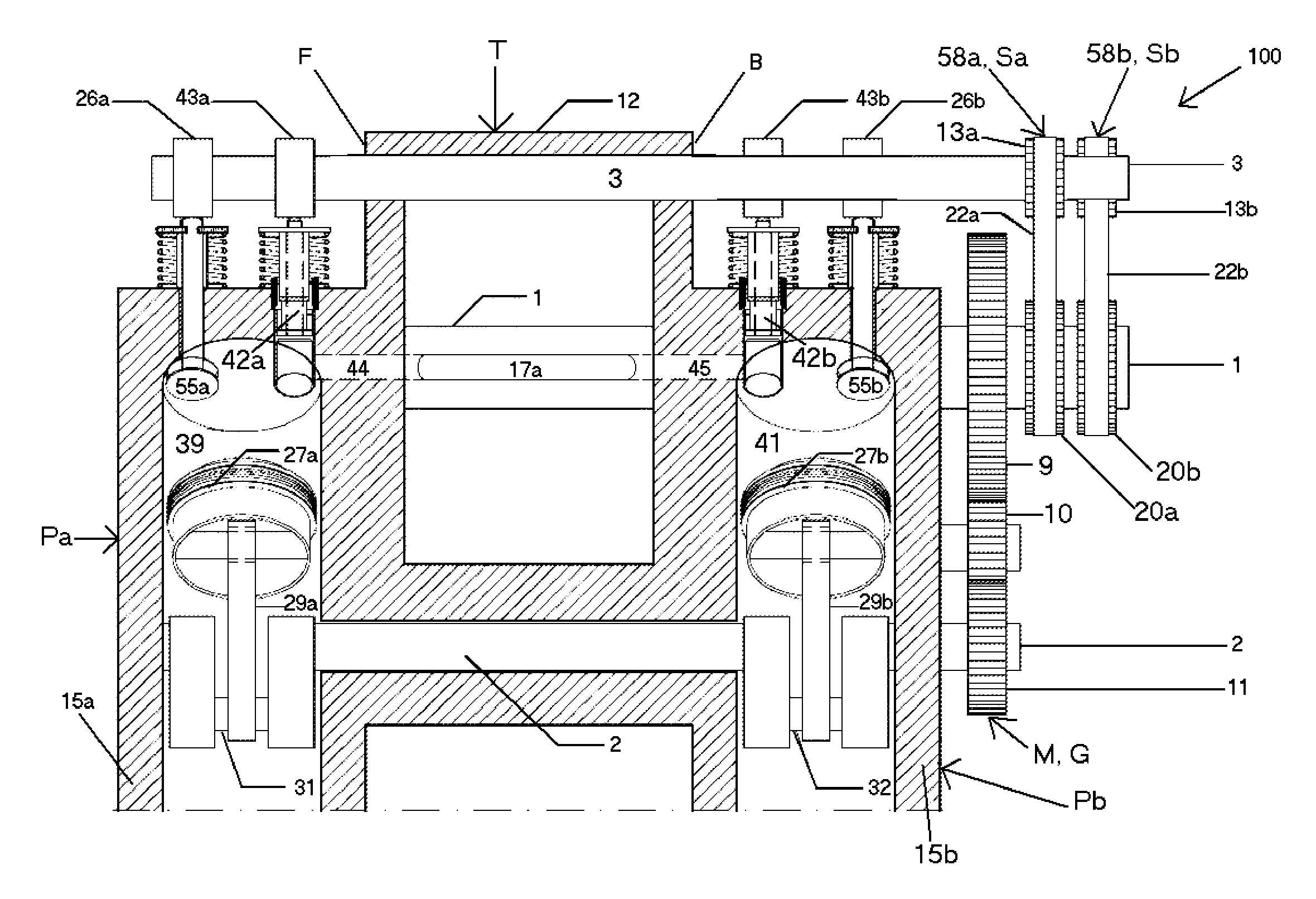
[0047]The present invention relates to an internal combustion engine in which an air intake stroke and a partial air compression stroke occur in at least two piston assemblies and in which full compression as well as the power stroke and the exhaust stroke occur in a separate adjacent turbine assembly.

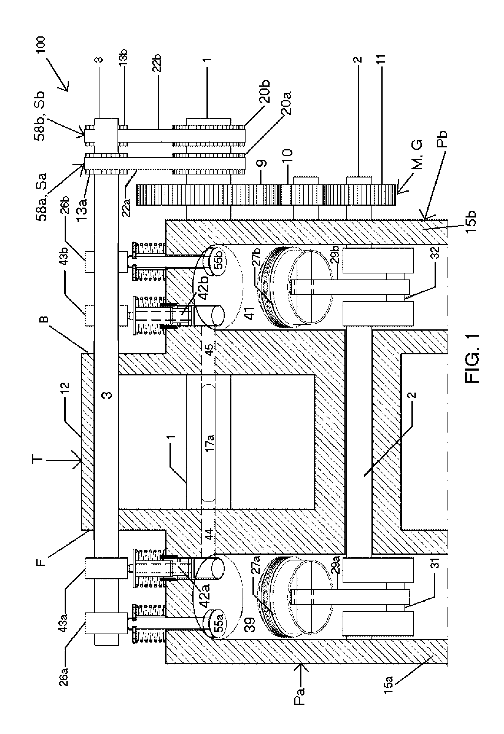
[0048]Referring now to the drawings, in which like reference numerals are used to refer to the same or similar elements, FIG. 1 shows a longitudinal cross section of the general assembly of a variable blade turbine internal combustion engine 100, according to an embodiment of the present invention.

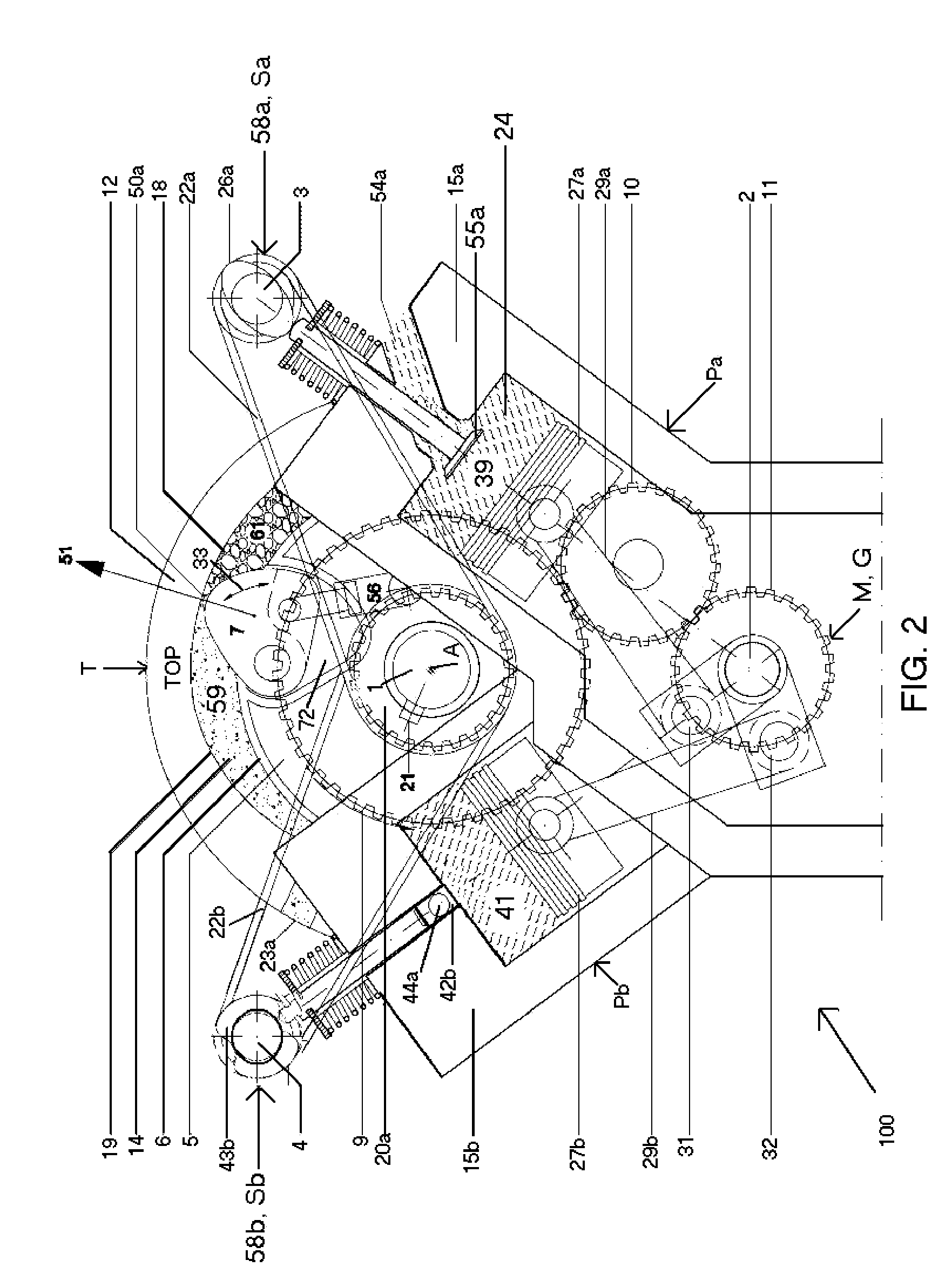
[0049]the main components of the present invention as illustrated in FIGS. 1 and 2, include a variable blade turbine assembly T (“turbine assembly”) which converts the energy created by combustion in its chambers 14 into rotational energy; an output shaft 1 which transfers rotational energy out of the turbine assembly T for use both outside and in other parts of the engine; a front piston / cyl...


PUM


Abstract

Internal combustion engine has intake with compression in piston/cylinders and combustion and exhaust in a turbine. Turbine assembly includes a rotor connected to an output shaft and has variable blades pivotally mounted to rotor. The output shaft is connected to a crankshaft that is connects to the pistons to synchronizes intake and compression with combustion and exhaust. While the rotor spins centrifugal force causes the blades to swivel outwardly. The blades swivel inboard of the rotor as the space between them and the turbine housing cam contour gradually decreases. After partial compression, air enters the turbine assembly's combustion and exhaust chamber. Once full compression is attained, combustion takes place initiating a power cycle causing the turbine to rotate. When the power cycle is completed, the inner cam contour forces the blades inboard and exhaust is cleared by the subsequent variable blade, facilitating the next combustion and exhaust cycle.

Description

FIELD AND BACKGROUND OF THE INVENTION[0001]The present invention relates generally to the field of internal combustion engines and in particular to an engine in which air intake and compression take place in the chambers of at least two piston / cylinder assemblies and combustion and exhaust take place in the chambers of a turbine assembly.[0002]Rotary engines with pistons pivotally mounted on a rotating rotor have been in the engine art for some time. For example, U.S. Pat. No. 1,349,353 to Wilber discloses a rotary engine and a lever arm fixed thereon having a roller upon its end. At the same end of the motor and around a shaft is hung a cam having raised portions upon its surface, upon which the roller of the lever arm is made to bear. As the roller is moved over the cam, the hinged pistons are moved completely into the combustion chambers at the time the rollers reach the summit of the raised portions of the cams, and are permitted to move out again as the roller drops or moves of...

Claims


Application Information

Patent Timeline
IPC IPC(8): F02B53/00
CPCF01C1/44F01C11/008Y02T10/17F02B53/04F02B33/06Y02T10/12
Inventor SAMUELS, SAMUEL LEE
Owner SAMUELS SAMUEL LEE
Why Eureka
Try Eureka