Photovoltaic module containing a metal/polymer stack for enhanced cooling and reflection

a technology of photovoltaic modules and metal/polymer stacks, applied in photovoltaics, electrical devices, semiconductor devices, etc., can solve the problems of not being thermally conductive, not filling lamination materials, complex and expensive process, etc., and achieve the effect of improving the efficiency of silicon pv cell modules

Inactive Publication Date: 2011-03-03
PEDDADA SATYANARAYANA RAO
View PDF7 Cites 2 Cited by
  • Summary
  • Abstract
  • Description
  • Claims
  • Application Information

AI Technical Summary

Benefits of technology

[0012]In accordance with the foregoing and other objectives, an aspect of the invention improves the efficiency of silicon PV cell modules and thin film PV modules by providing a means for defining a thermally conductive path characterized by a steep thermal gradient (delta T) interiorly, adjacent the back surface of the solar cells and having opposite ends extending exteriorly around at least a portion of a back facing exterior surface of the PV module. Heat developed from the solar cells is efficiently conducted away from the solar cells along the steep thermal gradient to the exterior shaded surface of the PV module where heat is quickly dissipated to the ambient surroundings. The means for providing a thermally conductive path may comprise a metal sheet or foil characterized by high reflectance with respect to the solar spectrum.

Problems solved by technology

In such a conventional thin film PV module, providing reflectance to the back of the thin film stack is complex and expensive, since it requires extra process steps, adds process time, and would require significant capital expenditure for processing equipment.
A further disadvantage in the construction of a conventional thin film PV module is that the lamination materials are not filled and are not thermally conductive.
Conventional thin film lamination materials tend to be thermally insulative and disadvantageously cause retention of heat upon prolonged exposure to the sun.
Both PV cells and their associated modules exhibit reduced efficiency as their temperature increases.

Method used


Image

  • Photovoltaic module containing a metal/polymer stack for enhanced cooling and reflection
  • Photovoltaic module containing a metal/polymer stack for enhanced cooling and reflection
  • Photovoltaic module containing a metal/polymer stack for enhanced cooling and reflection

Examples


Embodiment Construction

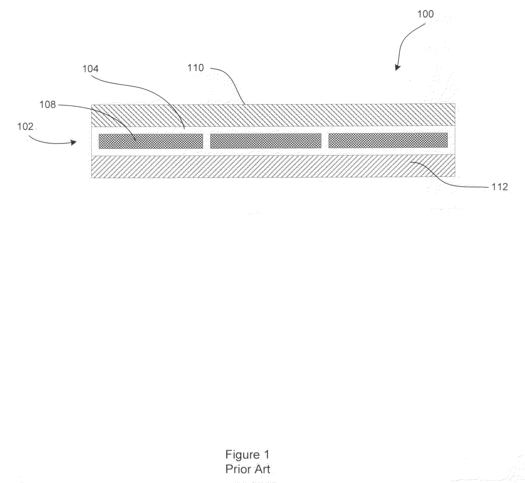
[0024]Referring to the drawings, FIG. 1 shows a cross section of a conventional single crystal silicon (x-Si) or polysilicon (p-Si) module 100. Silicon module 100 comprises a plurality of PV cells 102 enclosed in a laminated plastic 104. Such x-Si and p-Si modules do not have back glass, but instead use a PVF back sheet that provides a moisture barrier.

[0025]The lamination plastic adjacent the light incident planes 108 of PV cells 102 is transparent. A front cover glass 110 is provided adjacent the transparent lamination plastic for protection against the elements. The backside of the lamination plastic is typically sealed with a PVF film 112 such as Dupont TEDLAR® or other fluoro polymer. Moisture penetration and condensation on the PV cells is responsible for the majority of long term PV module failures. The most vulnerable sites for moisture penetration are at the interface between the cells and encapsulating lamination material 104, and at the interfaces between the glass 110, l...


PUM


Abstract

A method and apparatus for efficiently cooling a PV module for converting solar radiation to electrical energy comprises a means for defining a thermally conductive path characterized by a steep thermal gradient (delta T) provided interiorly, adjacent the back surface of the solar cells and having opposite ends extending exteriorly around at least a portion of a back facing exterior surface of the PV module. Heat developed from the solar cells is efficiently conducted away from the solar cells along the steep thermal gradient to the exterior shaded surface of the PV module where heat is quickly dissipated to the ambient surroundings. The invention applies to both polycrystalline and single crystalline, as well as to thin film PV modules.

Description

CROSS REFERENCE TO RELATED APPLICATION[0001]This application claims the benefit of U.S. patent application Ser. No. 12 / 583, 888, filed Aug. 26, 2009.BACKGROUND[0002]1. Field of the Invention[0003]The field of the invention relates generally to photovoltaic (PV) modules. In particular, the field of the invention pertains to thin film PV modules and to PV modules constructed from conventional x-Si or p-Si cells, wherein a metal / polymer stack characterized by a high back reflectance and high thermal conductivity is provided for defining a low resistance thermal path for conducting heat from inside the PV module to the external ambient surroundings for increased cooling and improved photovoltaic efficiency.[0004]2. Background of Related Art[0005]This invention applies to thin film PV modules and to PV modules constructed from conventional x-Si (single crystal silicon) or p-Si (polysilicon) cells. Such x-Si and p-Si modules do not have back glass, but instead use a polyvinyl fluoride (PV...

Claims


Application Information

Patent Timeline
Patent Type & Authority Applications(United States)
IPC IPC(8): H01L31/052
CPCY02E10/50H01L31/052H02S40/42
Inventor PEDDADA, SATYANARAYANA RAO
Owner PEDDADA SATYANARAYANA RAO
Why Eureka
Try Eureka