Filtered ASE Swept Source for OCT Medical Imaging

a swept source and filtered ase technology, applied in the field of swept source for oct medical imaging, can solve the problems of tunable lasers using ubiquitous semiconductor gain media generally only tuning well in one direction, degrade the performance of oct systems, and laser-based swept sources, etc., to achieve a higher performance system and low cost

Inactive Publication Date: 2011-03-03
EXCELITAS TECH
View PDF100 Cites 44 Cited by
  • Summary
  • Abstract
  • Description
  • Claims
  • Application Information

AI Technical Summary

Benefits of technology

[0010]In general, according to one aspect, the invention features an integrated filtered ASE swept source with amplifier and tracking filter. This source comprises a micro optical bench, a source for generating broadband light, a first tunable Fabry Perot filter, installed on the bench, for spectrally filtering the broadband light from the broadband source to generate a tunable signal, an amplifier, installed on the bench, for ampl

Problems solved by technology

The use of laser-based swept sources, however, does create problems.
This spectral structure of the laser emission increases relative intensity noise (RIN), which degrades perf

Method used


Image

  • Filtered ASE Swept Source for OCT Medical Imaging
  • Filtered ASE Swept Source for OCT Medical Imaging
  • Filtered ASE Swept Source for OCT Medical Imaging

Examples


first embodiment

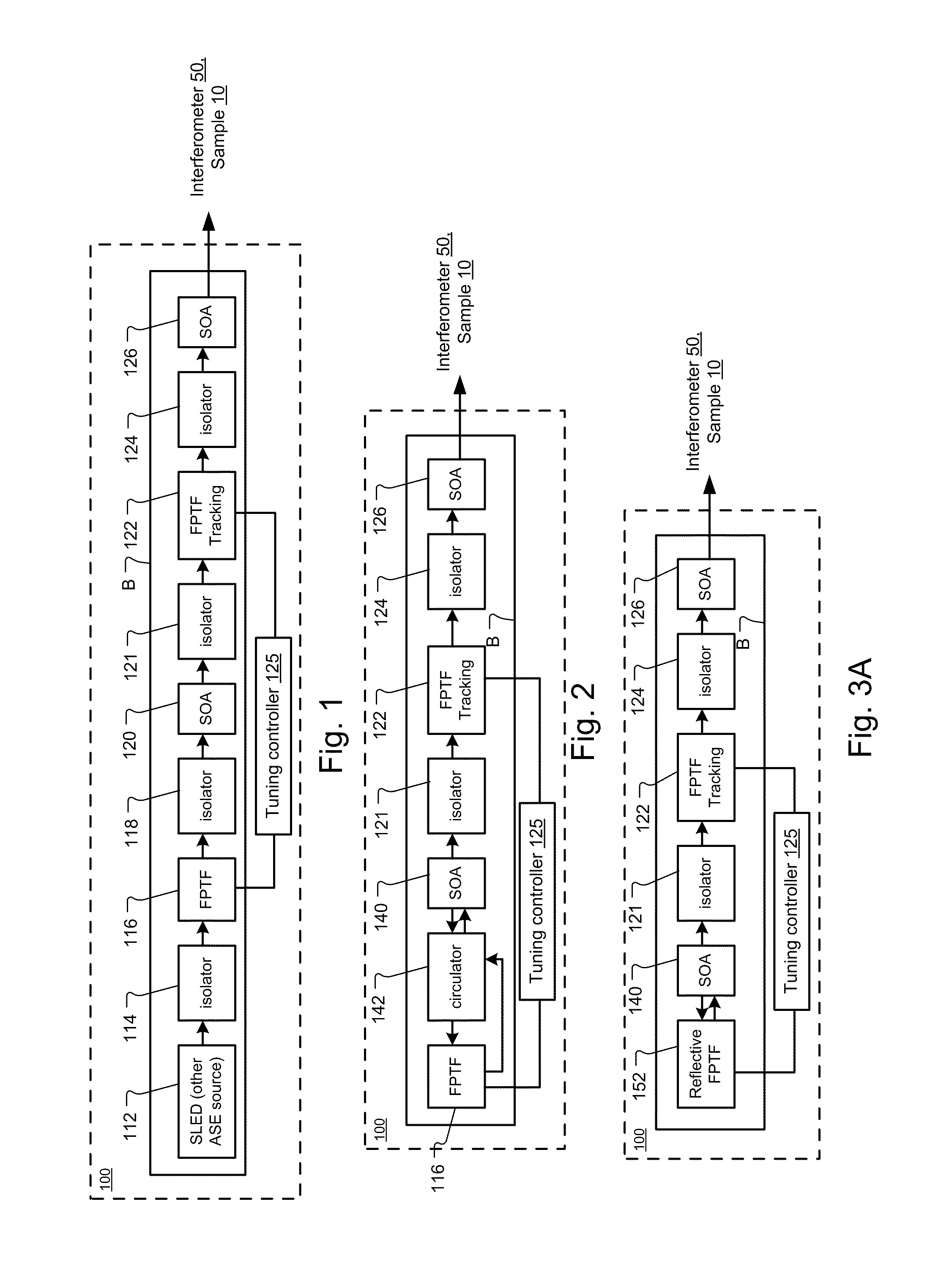
[0029]FIG. 1 shows a first embodiment swept optical source 100 that has been constructed according to the principles of the present invention.

[0030]The swept source 100 comprises a broadband source 112 that generates a broadband optical signal. In general, the broadband signal is characterized by a continuous spectrum that extends in wavelength over at least 40 nanometers (nm) of bandwidth, full width half maximum (FWHM). Typically, the continuous spectrum extends over at least 70 nm and preferably over 100 nm or greater.

[0031]In the preferred embodiment, the broadband source 112 is an electrically pumped semiconductor chip gain medium that is bonded or attached to a bench B. Common examples of the source 110 include superluminescent light emitting diodes (SLED) and semiconductor optical amplifiers (SOA). The material system of the chip is selected based on the desired spectral operating range. Common material systems are based on III-V semiconductor materials, including binary mate...

second embodiment

[0047]FIG. 2 shows a second embodiment swept optical source 100 that has been constructed according to the principles of the present invention.

[0048]In this example, a first optical amplifier 140 functions in a combined role, both as a broadband ASE source and a first amplification stage. In more detail, a broadband signal is generated at a front facet of the first optical amplifier 140, preferably an SOA as described above. This broadband signal is generated by the ASE emissions of first optical amplifier 140. These emissions are coupled to a first tunable filter 116. In construction and design, the first tunable filter 116 is preferably as described in connection with the first embodiment.

[0049]The tunable signal produced by the first tunable filter is then coupled back into the front facet of the first optical amplifier 140 via an optical circulator 142. The first optical amplifier then amplifies the tunable signal, which is transmitted out of its back facet.

[0050]The amplified t...

third embodiment

[0052]FIG. 3A shows a third embodiment swept optical source 100 that has been constructed according to the principles of the present invention.

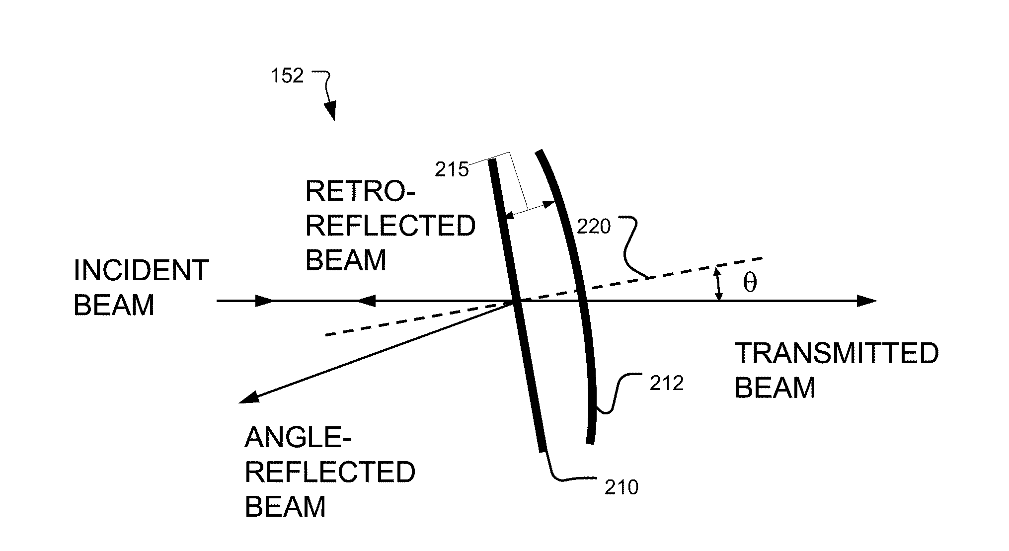
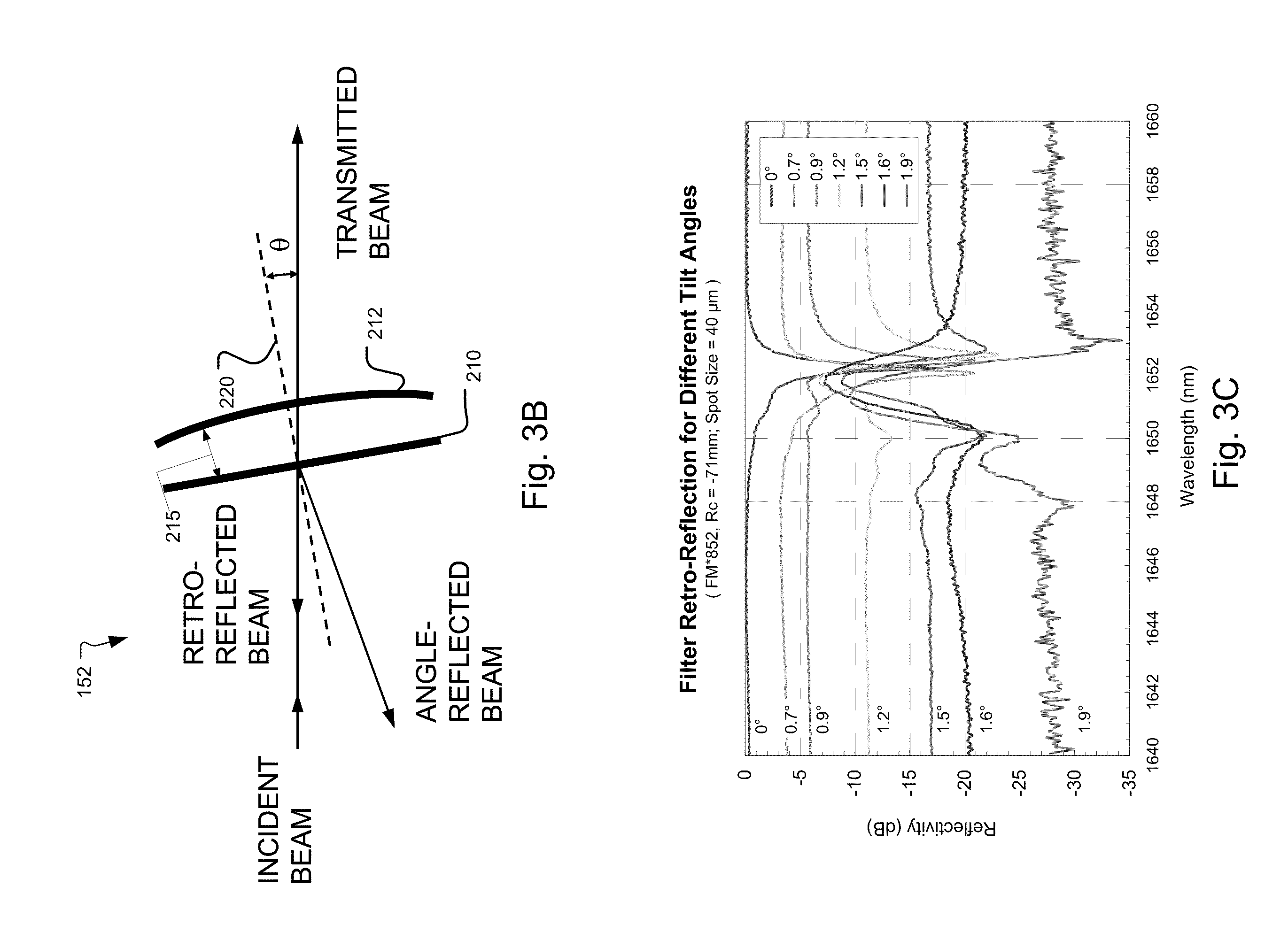
[0053]In common with the second embodiment, a first optical amplifier 140 functions in a combined role, both as a broadband ASE source and a first amplification stage. The need for the circulator is avoided by the use of a reflective narrow-band tunable filter 152 that is preferably bonded to the bench B. This element reflects only a narrowband bandwidth tunable signal.

[0054]Otherwise, the third embodiment functions as described in connection with the second embodiment, with the narrowband signal being amplified by the first optical amplifier 140. This narrowband signal is generated by the filtered ASE emissions of first optical amplifier 140. The amplified tunable signal is then further amplified, conditioned, and filtered by an optical train of elements isolator 121, tracking filter 122, isolator 124, and SOA 126 as described in connection ...


PUM


Abstract

An integrated swept wavelength optical source uses a filtered ASE signal with an optical amplifier and tracking filter. This source comprises a micro optical bench, a source for generating broadband light, a first tunable Fabry Perot filter, installed on the bench, for spectrally filtering the broadband light from the broadband source to generate a narrowband tunable signal, an amplifier, installed on the bench, for amplifying the tunable signal, and a second tunable Fabry Perot filter, installed on the bench, for spectrally filtering the amplified tunable signal from the amplifier. A self-tracking arrangement is also possible where a single tunable filter both generates the narrowband signal and spectrally filters the amplified signal. In some examples, two-stage amplification is provided. The use of a single bench implementation yields a low cost high performance system. For example, polarization control between components is no longer necessary.

Description

BACKGROUND OF THE INVENTION[0001]Optical coherence analysis relies on the use of the interference phenomena between a reference wave and an experimental wave or between two parts of an experimental wave to measure distances and thicknesses, and calculate indices of refraction of a sample. Optical Coherence Tomography (OCT) is one example technology that is used to perform usually high-resolution cross sectional imaging. It is often applied to imaging biological tissue structures, for example, on microscopic scales in real time. Optical waves are reflected from an object or sample and a computer produces images of cross sections of the object by using information on how the waves are changed upon reflection.[0002]The original OCT imaging technique was time-domain OCT (TD-OCT), which used a movable reference mirror in a Michelson interferometer arrangement. More recently Fourier domain OCT (FD-OCT) has been developed. Two related FD-OCT techniques are time encoded and spectrum encoded...

Claims


Application Information

Patent Timeline
IPC IPC(8): G01B9/02G02B5/22
CPCG01J3/10G01J3/26G01J3/4338G02B5/22G01B9/02004G01B9/02091G01N21/4795
Inventor FLANDERS, DALE C.ATIA, WALID A.KUZNETSOV, MARK E.
Owner EXCELITAS TECH
Why Eureka
Try Eureka