

Efficient linear linc power amplifier
a linear linc power amplifier and linear technology, applied in the direction of amplifier combination, digital transmission, transmission, etc., can solve the problems of reducing the efficiency of the combiner, imposing significant linearity constraints on the output stage amplifier, and limited bandwidth available for transmitting information, so as to improve the linear power amplification of rf signals and high efficiency
- Summary
- Abstract
- Description
- Claims
- Application Information
AI Technical Summary
Benefits of technology
Problems solved by technology
Method used
Image

Examples
second embodiment
[0079]FIG. 10 shows the invention, where again the class-DE PA 400 (referred to as 400*) of FIG. 4 is combined with a second class-DE PA 400** to form an out-phasing PA 1000. The inductor Lx has been conveniently incorporated in the combiner structure 1031 to save on the total component count. Any parasitic capacitance of the transformer structure 1031 adds to the total parasitic capacitance of the device 1000. It is noted that a parallel resonant tank at the output may alternatively be used instead of the series resonator tank 1050. Then, the output inductor Lx / 2 can be merged with the parallel resonator tank. It is further worth to be noted that the load resistance of this structure is 4 times smaller as in the embodiment of FIG. 6 due to the transformation properties of this network.
fourth embodiment
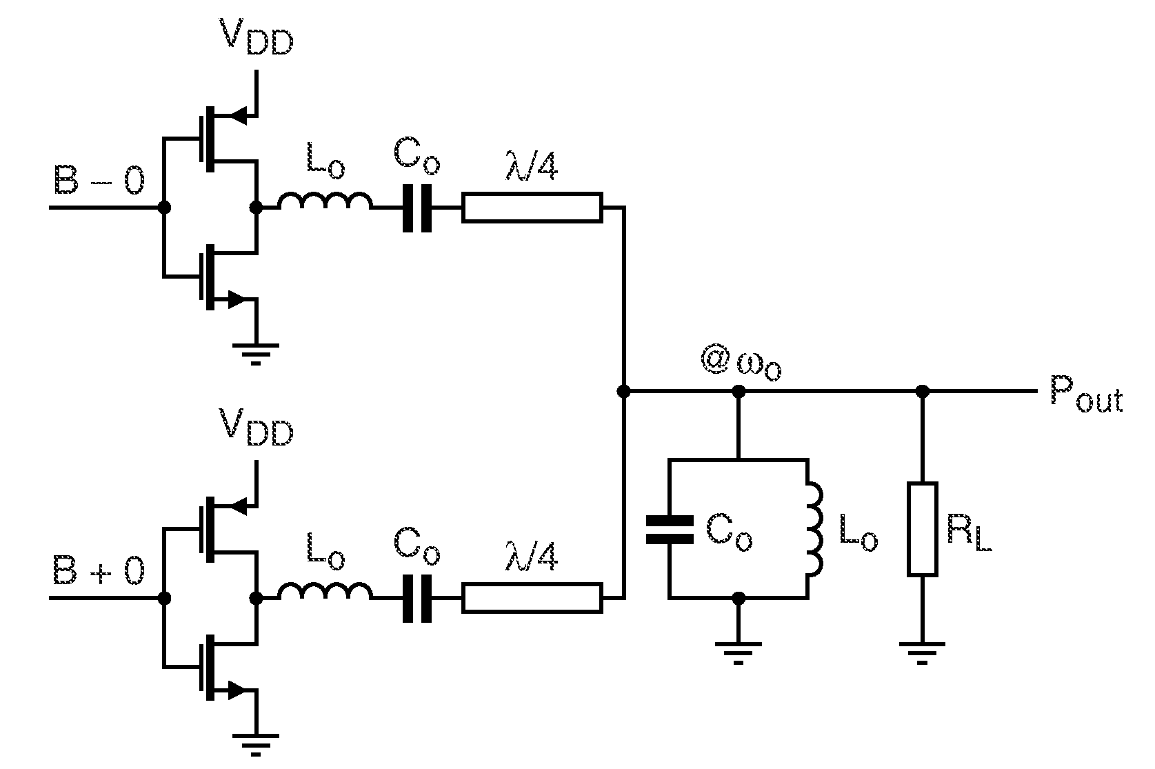
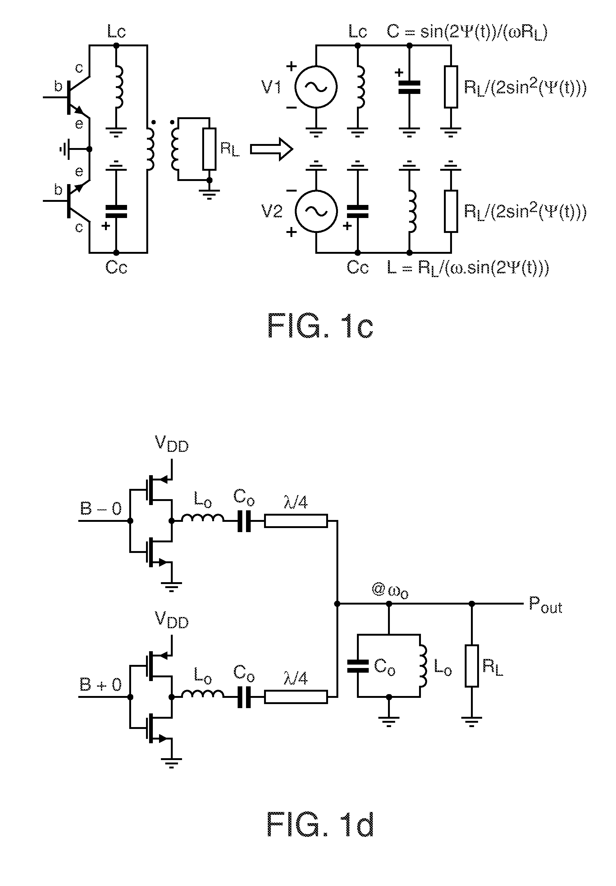
[0080]FIG. 11 and FIG. 12 show a third and fourth embodiment of the invention, where the class-DE PA 400 (referred to as 400*) of FIG. 4 is combined with a second class-DE PA 400** to form an out-phasing PA 1100 or 1200, respectively, and where a transmission line combiner 1131 or 1231, respectively, is used as shown in FIG. 1d. The difference is that the amplifiers 400*, 400** are operated in class-DE mode by including the parallel inductors Lx and operating the amplifiers 400*, 400** at a duty-cycle d<0.5 (50%) to accommodate zero-voltage switching during the dead time.
[0081]It will be appreciated that, as in all embodiments of the present invention, the combiner 1130 or 1230, respectively, can be made non-coherent according to the second aspect of the invention by including a respective reactive component B1 at either one of the outputs of the two PAs 400*, 400** or by having respective different parallel inductors Lx and Lx* in both paths to make the paths electrically asymmetri...
fifth embodiment
[0083]FIG. 13 shows the invention, which is based on a push-pull transformer coupled class-DE circuit arrangement 1300. This configuration is a more practical implementation of the general schematic shown in FIG. 3. The transformer-coupled implementation may advantageously be considered when no complementary switching devices S1-S4 are available in the used technology. Moreover, the output signals of both amplifiers 310, 320 can be easily summed by just stacking the transformers 1331, 1332.
[0084]It is noted that, as in the first and second embodiment, the class-DE reactive components Lx have been conveniently incorporated in the transformer design itself, which saves on the component count again. Further, any parallel capacitance of the transformers 1331, 1332 can be added to the parasitic capacitance of the PA 1300 itself.
PUM
 Abstract
Description
Claims
Application Information