Frequency synthesis system with self-calibrated loop stability and bandwidth

a frequency synthesis and self-calibration technology, applied in the field of phaselocked loops, can solve the problems of increasing the development cost of different pll designs and tests, the difficulty of design, and the jitter of the wimax receiver, so as to achieve the effect of low jitter, more load capacitance, and low voltage environmen

Inactive Publication Date: 2011-03-17
SUNPLUS TECH CO LTD
View PDF20 Cites 24 Cited by
  • Summary
  • Abstract
  • Description
  • Claims
  • Application Information

AI Technical Summary

Benefits of technology

[0015]A first object of the present invention is to provide a frequency synthesis system with self-calibrated loop stability and bandwidth, in which a damping factor and a bandwidth-to-reference frequency ratioωnωREFis independent of a value of frequency division of a programmable frequency divider.
[0016]A second object of the present invention is to provide a frequency synthesis system with self-calibrated loop stability and bandwidth, which is capable of receiving different input reference frequencies in order to allow a damping factor ζ and a bandwidth-to-reference frequency ratioωnωREFto be designed constants, thereby obtaining the response speed optimization and the stability.
[0017]A third object of the present invention is to provide a frequency synthesis system with self-calibrated loop stability and bandwidth, which compensates a controllable oscillator and selects an output signal when the output signal presents a wideband distribution, and the damping factor and the bandwidth-to-reference frequency ratio are sharply changed. Therefore, the damping factor ζ and the bandwidth-to-reference frequency ratioωnωREFare provided with the best system response speed and stability by means of the compensation technique.
[0018]A fourth object of the present invention is to provide a frequency synthesis system with self-calibrated loop stability and bandwidth, which allows a discrete time loop filter to be implemented with a small area into an integrated circuit.
[0019]A fifth object of the present invention is to provide a frequency synthesis system with self-calibrated loop stability and bandwidth, which has low jitter and wideband features and can be operated in a low voltage environment.
[0020]A sixth object of the present invention is to provide a frequency synthesis system with self-calibrated loop stability and bandwidth, which includes a capacitance bank controller to dynamically set a capacitance bank to a value to thereby provide more load capacitance to each stage of delay and eliminate more phase error from a VCO.

Problems solved by technology

In wireless receiving systems, a widely adaptive frequency synthesizer for television receivers, WiMax receivers and the like is a tough challenge on design.
Such a way increases complication in management and also development cost for different PLL designs and tests.
Such a way increases the managing trouble and the developing cost for designing and testing the different PLLs.
Another solution is to design a single PLL applicable for different ICs, but how to design a PLL for a wideband operation is a challenge.
When the frequency requirement is met, another challenge is in the purity of the PLL output frequency, i.e., the output jitter, or known as the phase noise, in terms of characterized specification.
The PLL can produce a pure and stable clock, but noises can affect the clock stability.
After the system is operated for a long time, the long-term jitter may affect the system significantly.
The long-term jitter often makes the system working point drift.
The periodic jitter is caused by the imbalance or current leakage of a charge pump, which produces a static phase offset between the output signal and a reference signal.
In the deep submicron technology, due to the shortened processes, the current leakage is increased exponentially.
In addition, for a low voltage and wide operating range requirement, a typical PLL has a very high VCO regulation sensitivity, which makes the periodic jitter become worse.
The long-term jitter is caused by a VCO phase error.

Method used


Image

  • Frequency synthesis system with self-calibrated loop stability and bandwidth
  • Frequency synthesis system with self-calibrated loop stability and bandwidth
  • Frequency synthesis system with self-calibrated loop stability and bandwidth

Examples


Embodiment Construction

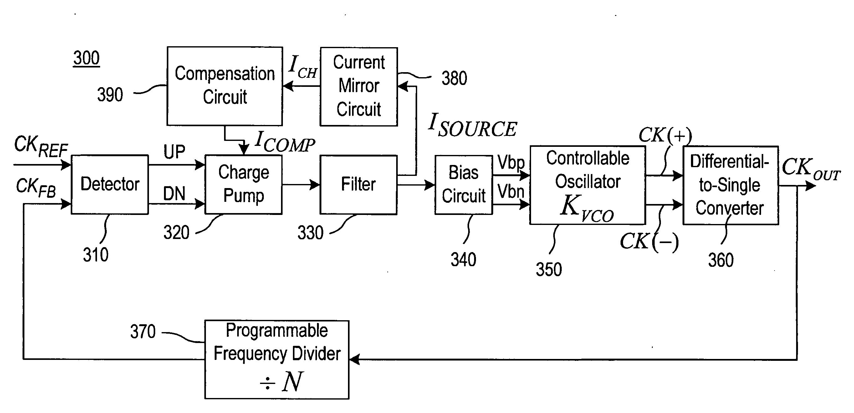
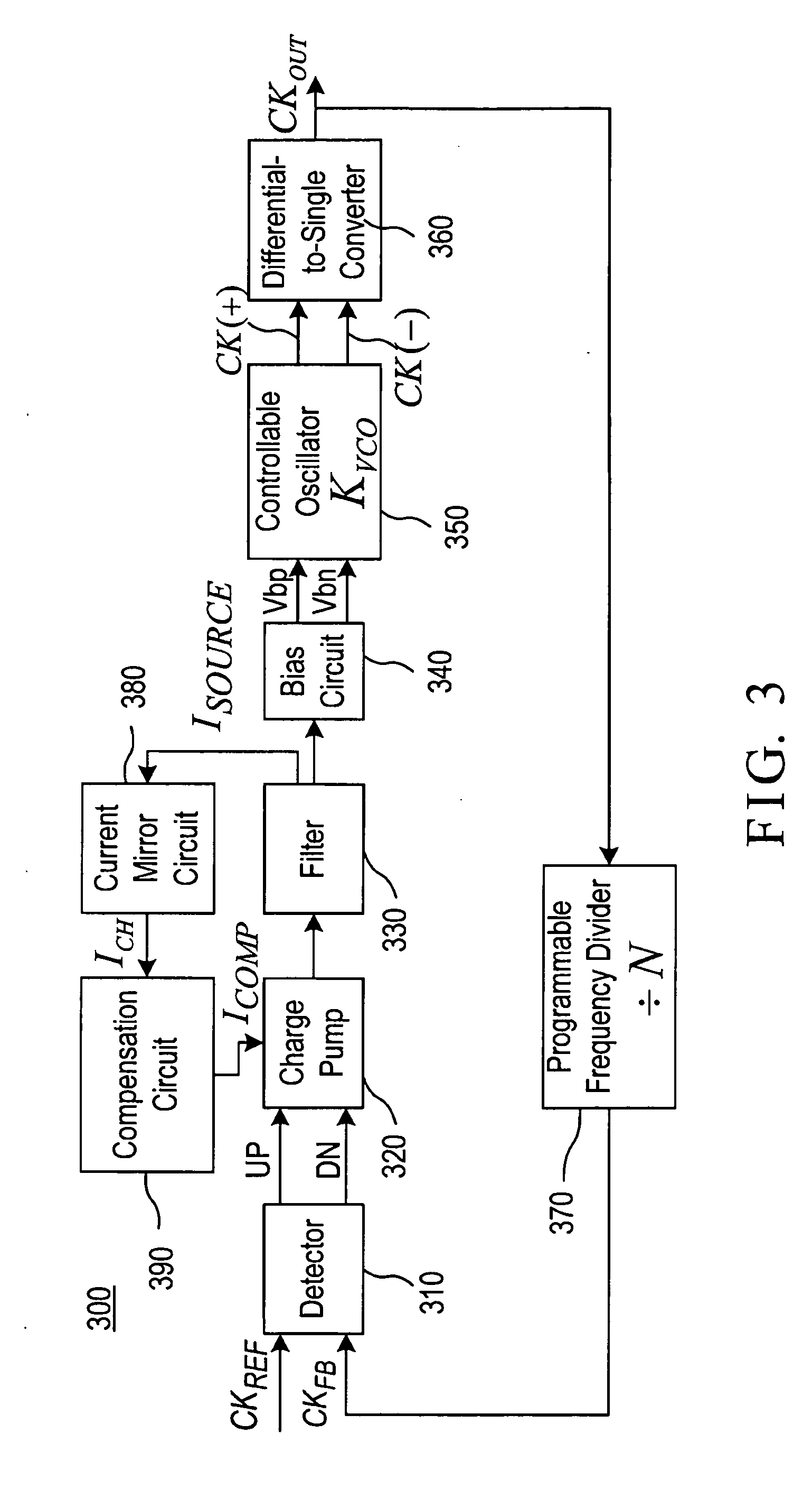
[0040]FIG. 3 is a block diagram of a frequency synthesis system 300 with self-calibrated loop stability and bandwidth according to an embodiment of the invention. The system 300 produces an output signal based on an input signal. In FIG. 3, the system 300 includes a detector 310, a charge pump 320, a filter 330, a bias circuit 340, a controllable oscillator 350, a differential-to-single converter 360, a programmable frequency divider 370, a current mirror circuit 380 and a compensation circuit 390.

[0041]The detector 310 produces a detection signal based on a logic level difference between the input signal CKREF and a feedback signal CKFB The detector 310 adjusts the detection signal based on a phase leading or lagging relationship between the input signal CKREF and the feedback signal CKFB. The detection signal includes a frequency up signal UP and a frequency down signal DN.

[0042]When the phase of the input signal CKREF lags that of the feedback signal CKFB, the detector 310 output...


PUM


Abstract

In a frequency synthesis system with self-calibrated loop stability and bandwidth, a detector produces a detection signal based on a difference between an input signal and a feedback signal; a charge pump produces a control signal based on the detection signal; a filter produces a tuning signal and a source current based on the control signal; a bias circuit produces first and second bias signals; a controllable oscillator produces a differential output signal with a selected specific frequency; a differential-to-single converter produces an output signal with the selected specific frequency; a programmable frequency divider produces the feedback signal; a current mirror circuit receives the source current for producing a mirror current; a compensation circuit produces a compensation current based on the mirror current for compensating the variation of the damping factor and the bandwidth-to-reference frequency ratio.

Description

BACKGROUND OF THE INVENTION[0001]1. Field of the Invention[0002]The present invention relates to the technical field of phase-locked loop (PLL) and, more particularly, to a frequency synthesis system with self-calibrated loop stability and bandwidth.[0003]2. Description of Related Art[0004]In wireless receiving systems, a widely adaptive frequency synthesizer for television receivers, WiMax receivers and the like is a tough challenge on design. For each output frequency of the frequency synthesizer, the parameters (such as the frequency of an input signal, a multiplication factor, etc.) have to be accurately adjusted for minimizing the phase noises and maintaining the stability of the frequency synthesizer.[0005]In the frequency synthesizer, the loop bandwidth indicates the response speed, and preferably is 1 / 20 of the reference frequency. The damping factor indicates the stability of the frequency synthesizer, and is preferably close to one. The systematic parameters above are rela...

Claims


Application Information

Patent Timeline
Patent Type & Authority Applications(United States)
IPC IPC(8): H03L7/06
CPCH03L7/093H03L2207/04H03L7/0995
Inventor CHEN, CHUN-LIANGHSU, HUI-CHUN
Owner SUNPLUS TECH CO LTD
Why Eureka
Try Eureka