Light emitting device, illumination device, and photo sensor

a technology illumination devices, which is applied in the direction of vehicle headlamps, photometry, optical radiation measurement, etc., can solve the problems of limiting the downsizing degree of light emitting devices, harmful to the human eye, and low power per led element, so as to improve the sensitivity to light, enhance the intensity of light detected, and improve the safety of the human body

Active Publication Date: 2011-03-17
SHARP FUKUYAMA LASER CO LTD
View PDF8 Cites 149 Cited by
  • Summary
  • Abstract
  • Description
  • Claims
  • Application Information

AI Technical Summary

Benefits of technology

[0041]In the light emitting device, in which the semiconductor laser element emits laser light that has a wavelength equal to or less than 500 nm, it is preferred that the optical conversion member convert at least a portion of the laser light emitted from the semiconductor laser element into incoherent light having a wavelength longer than 500 nm. This way, with the use of, for example, an optical filter that blocks light having a wavelength of 500 nm or less and transmits light having a wavelength longer than 500 nm, or an optical filter that blocks light having a wavelength longer than 500 nm and transmits light having a wavelength of 500 nm or less, it is easy to block one of light that has substantially the same wavelength as that of laser light and incoherent light while transmitting at least a portion of another one of the light that has substantially the same wavelength as that of laser light and the incoherent light.
[0042]In the light emitting device, in which the optical conversion member converts at least a portion of the laser light into incoherent light having a wavelength longer than 500 nm, it is preferred that the semiconductor laser element emit one of blue laser light, blue-violet laser light, and ultraviolet laser light. With this structure, the wavelength of laser light emitted from the semiconductor laser element is approximately 450 nm or less. A larger difference is consequently created between the wavelength of laser light emitted from the semiconductor laser element (wavelength approximately equal to or less than 450 nm) and the wavelength of incoherent light obtained through wavelength conversion by the optical conversion member (wavelength longer than 500 nm). As a result, with the use of an optical filter, it is even easier to block one of light that has substantially the same wavelength as that of laser light and incoherent light while transmitting at least a portion of another one of the light that has substantially the same wavelength as that of laser light and the incoherent light.
[0043]An illumination device according to a second aspect of the present invention includes the light emitting device structured as above. This structure improves the illumination device that uses the semiconductor laser element in safety to the eye.
[0044]A photo sensor according to a third aspect of the present invention is a photo sensor for use in a safety device of a light emitting device that includes an optical conversion member for converting coherent laser light emitted from a semiconductor laser element into incoherent light, and for emitting the incoherent light, in which the photo sensor detects intensity of at least one of the incoherent light and the coherent laser light exiting to an outside of the light emitting device. With this structure, the photo sensor reflects on its output a reduction in intensity of incoherent light obtained through a conversion by the optical conversion member, or an increase in intensity of laser light exiting to the outside. An optical conversion anomaly such as a chip in the optical convers

Problems solved by technology

However, the power per LED element is generally low and a light emitting device that is required to have high power needs to use a plurality of LED elements, thus limiting the degree of downsizing of the light emitting device.
However, when the powder optical conversion material which converts laser light into visible light is chipped off or otherwise develops a defect for some reason, it is a risk with this light emitting device that infrared light (laser light) emitted from the infrared ray generating device which is a laser light source (semiconductor laser element or the like) exits to the outside without being converted into visible light.
Laser light emitted from a semiconductor laser element is coherent light, and if exiting to the outside without being converted into visible light, may be harmful to the human eye.
This problem is particularly serious when this light emitting device is used as an illumination device such as an indoor illumination device, an automobile headlight, or a searchlight.
However, the light emitting device of JP 2003-295319 A also has a risk that a chip or other defects in the fluorescent substance 1006 cause the laser light 1002 to be reflected by the ultraviolet ray reflecting mirror 1007 and by the visible light reflecting mirror 1009 and to exit to the outside.
Further, in the case where blue laser light which is in the v

Method used


Image

  • Light emitting device, illumination device, and photo sensor
  • Light emitting device, illumination device, and photo sensor
  • Light emitting device, illumination device, and photo sensor

Examples


first embodiment

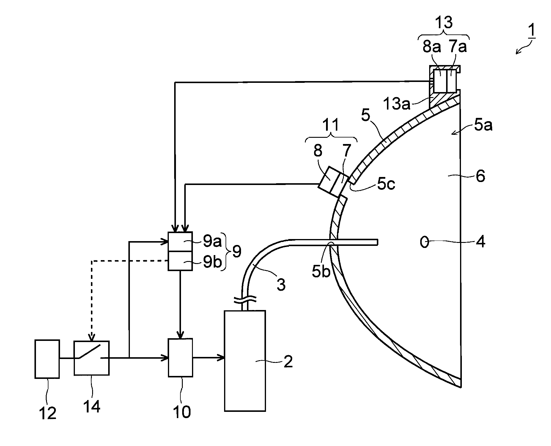
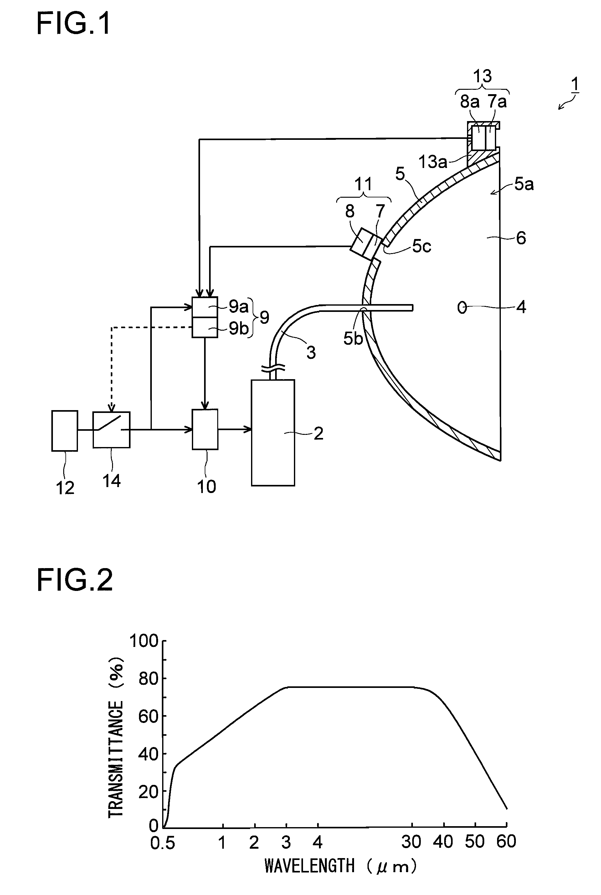
[0061]The structure of a light emitting device 1 according to a first embodiment of the present invention is described first with reference to FIGS. 1 to 3.

[0062]The light emitting device 1 according to the first embodiment of the present invention can be used also as an illumination device such as an automobile headlight, and includes components illustrated in FIG. 1. The components are: a semiconductor laser element 2 which functions as a laser light source (and emits, for example, blue-violet laser light); a light guiding member 3 which guides laser light emitted from the semiconductor laser element 2 into a concave part 5a of a reflecting member 5 constituting a parabolic mirror; a fluorescent substance 4 which is positioned at a focal point in the concave part 5a of the reflecting member 5 to be irradiated with laser light guided by the light guiding member 3 and to convert the laser light into visible light, mainly of a blue color, a green color, and a red color; a transparent...

second embodiment

[0129]In a second embodiment of the present invention, a case where an optical filter blocks, unlike the first embodiment, light subjected to wavelength conversion is described with reference to FIGS. 7 and 8.

[0130]A light emitting device 101 according to the second embodiment of the present invention includes, as illustrated in FIG. 7, a semiconductor laser element 102, which functions as a laser light source, a fluorescent substance 104, which is irradiated with laser light emitted from the semiconductor laser element 102, a holding member 106, which is placed within a concave part 105a of a reflecting member 105 to hold the fluorescent substance 104, an optical filter 107, which has a function of blocking light that has a given wavelength, a light receiving element 108, a control part 109, which is electrically connected to the light receiving element 108, and the driver circuit 10, which is electrically connected to the semiconductor laser element 102 and the control part 109. T...

third embodiment

[0146]A light emitting device 201 according to a third embodiment of the present invention includes, as illustrated in FIG. 9, a semiconductor laser element 202, which functions as a laser light source, a fluorescent substance 204, which is irradiated with laser light emitted from the semiconductor laser element 202, an optical filter 207, which has a function of blocking light that has a given wavelength, a light receiving element 208, the control part 9, which is electrically connected to the light receiving element 208, the driver circuit 10, which is electrically connected to the semiconductor laser element 202 and the control part 9, and a laser light blocking filter 213. The fluorescent substance 204 is an example of the “optical conversion member” of the present invention, and the optical filter 207 is an example of the “first optical filter” of the present invention. The laser light blocking filter 213 is an example of a “safety device” and a “second optical filter” of the p...


PUM


Abstract

Provided is a light emitting device improved in safety to an eye. The light emitting device includes: a semiconductor laser element for emitting laser light; an optical conversion member for converting coherent laser light which is emitted from the semiconductor laser element into incoherent light, and for emitting the incoherent light; and a safety device for preventing the coherent laser light from exiting to an outside.

Description

[0001]This application is based on Japanese Patent Application No. 2009-213380 filed on Sep. 15, 2009, the contents of which are hereby incorporated by reference.BACKGROUND OF THE INVENTION[0002]1. Field of the Invention[0003]The present invention relates to a light emitting device, an illumination device, and a photo sensor. In particular, the present invention relates to a light emitting device and an illumination device which include a semiconductor laser element, and to a photo sensor used in these devices.[0004]2. Description of Related Art[0005]In recent years, light emitting devices that use an LED have been attracting attention because an LED has a considerably longer lifetime than that of an incandescent lamp or a fluorescent lamp. Illumination devices and the like that use an LED as a white light emitting device have already been put into practical use. However, the power per LED element is generally low and a light emitting device that is required to have high power needs...

Claims


Application Information

Patent Timeline
IPC IPC(8): G08B17/12H01J40/14F21V11/00F21V9/00
CPCF21K9/00F21V23/0442F21S48/31F21S48/1145F21Y2101/025F21Y2115/30F21S41/16F21S41/176F21S45/70F21S45/10
Inventor KISHIMOTO, KATSUHIKO
Owner SHARP FUKUYAMA LASER CO LTD
Why Eureka
Try Eureka