Coated Capillary Electrophoresis Tubes and System

a capillary electrophoresis tube and electrophoresis tube technology, which is applied in the direction of coating, instruments, measurement devices, etc., can solve the problems of reducing the sample throughput through the capillary, affecting the reproducibility, and changing the electrosmotic flow velocity of the solution in the capillary, so as to facilitate the increase of the sample flow through the capillary and the density of positive charges

Inactive Publication Date: 2011-03-17
BECKMAN COULTER INC
View PDF2 Cites 0 Cited by
  • Summary
  • Abstract
  • Description
  • Claims
  • Application Information

AI Technical Summary

Benefits of technology

[0008]The inner surface of the capillary typically further comprises a second polymer layer covalently bonded to the first polymer layer. As compared to a single layer, this additional layer results in a higher density of positive charges on the wall surface that facilitates an increase in sample flow through the capillary. The second polymer layer has a plurality of polymer groups comprising (CH2CH2NH)x attached by a second linker group to a second anchor group that is covalently bonded to a first anchor group of a polymer group from the first polymer layer. In this formula, “x” represents an integer independently selected for individual polymer groups within the first polymer layer or second polymer layer. The first polymer layer covalently bonded to the inner-surface of the capilla

Problems solved by technology

This is a problem because the adsorption of analytes continuously changes the surface properties of the capillary tube, resulting in changes in the electrosmotic flow velocity of the solution in the capillary.
This causes a fluctuation of migration time of analytes which results in inaccuracies and poor reproducibility.
This approach can reduce the adsorption of an

Method used


Image

  • Coated Capillary Electrophoresis Tubes and System
  • Coated Capillary Electrophoresis Tubes and System
  • Coated Capillary Electrophoresis Tubes and System

Examples


example i

Preparation of Silica Capillary Tubes with a Cross-Linked Coating

[0030]Trimethoxysilylpropyl (polyethyleneimine) (PEI silane) is a linear polyethyleneimine attached to trimethoxy silyl propyl groups. PEI silane was dissolved in methanol to obtain a 5% (v / v) solution of PEI silane in methanol by vortexing for 3 min in a glass vial. A capillary tube was first treated with methanol, then water, and then with 1.0 N Sodium Hydroxide and 1.0 N hydrochloric acid. The capillary was rinsed with deionized water, and afterward with methanol. The PEI silane solution was pumped through the capillary for 12-16 h at room temperature. After this, the capillary was rinsed briefly with methanol. Next, a 10% (v / v) solution of 1,4-Butanediol diglicidylether (BUDGE) in 1,4-Dioxane was pumped through the capillary for 4-6 h at room temperature to cross-link those polymer chains. After this; nitrogen was passed through the capillary while heating it for 1.0 h at 80° C. The capillary was then rinsed thorou...

example ii

Comparison of Electrophoresis Run Profiles for Coated and Uncoated Capillary Tubes

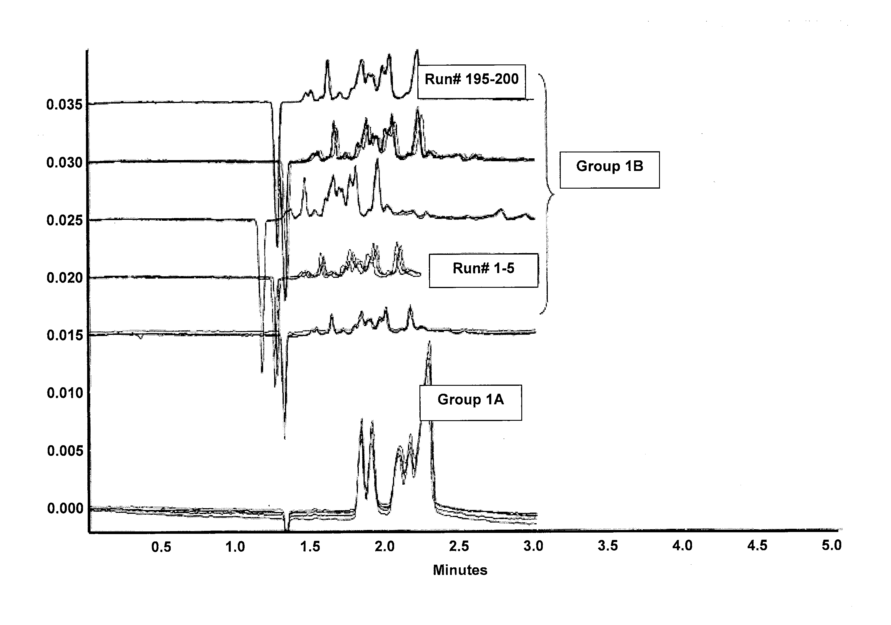
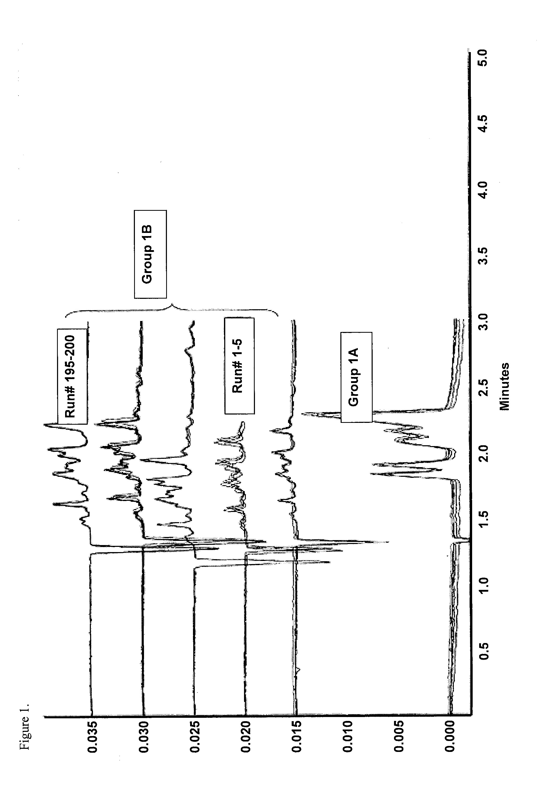
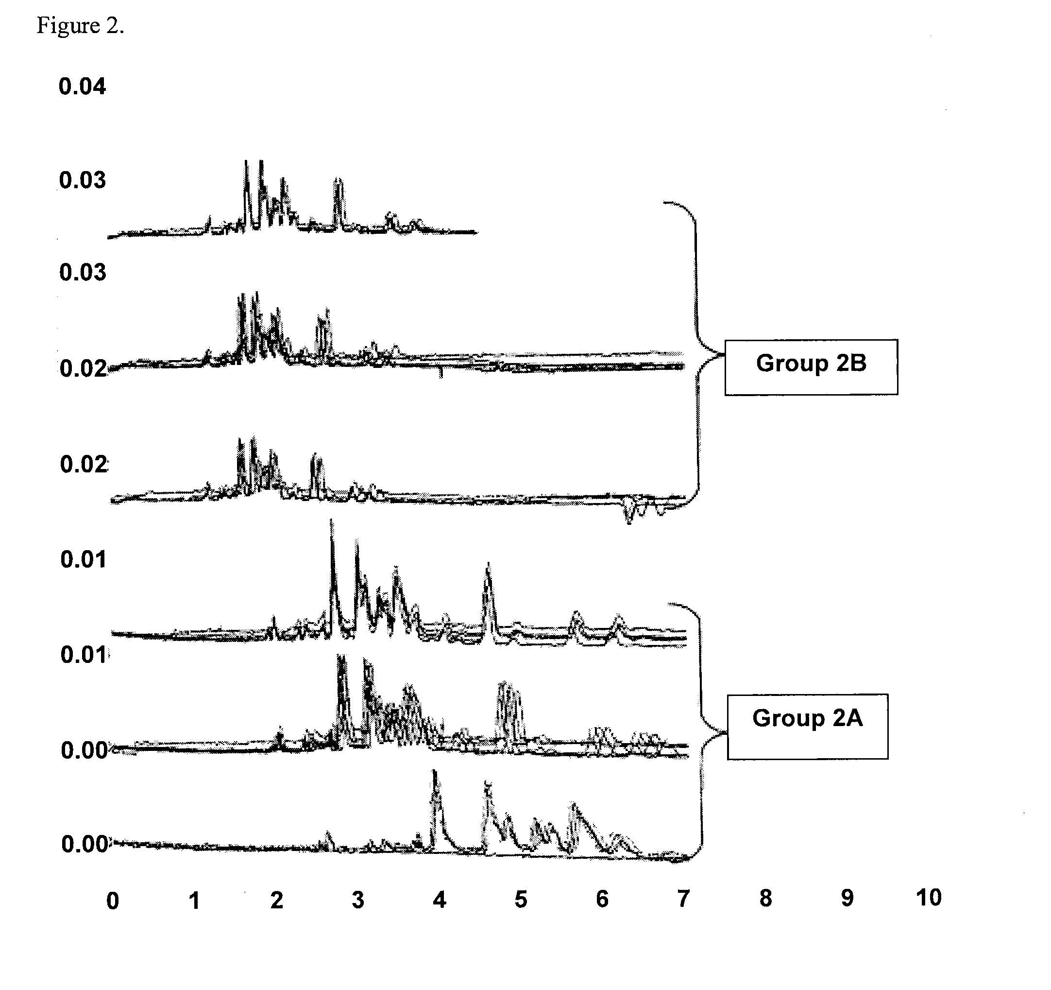
[0031]FIG. 1 illustrates separation profiles obtained from PEI silane and BUDGE coated fused silica capillary tubes. The capillary tubes had a 40 μm internal diameter, a 364 μm outer diameter, a 31 cm total length, and were coated according to example I. Electrophoresis was performed at 400 v / cm field strength on a Beckman Coulter P / ACE MDQ capillary electrophoresis system, available from Beckman Instruments, Inc. (Fullerton, Calif.). Group IA of FIG. 1 shows the electropherograms obtained from the first five runs of five peptide standards. Group 1B in FIG. 1 shows electropherograms obtained up to 200 runs of Horse heart Cytochrome c. The electropherogram shows that migration time of analytes were stable from the first run and thereafter, and that the electrophoretic separation took only 2.3 min to complete. FIG. 2 illustrates separation profiles obtained from bare uncoated fused silica capillary tubes...


PUM


Abstract

The invention is directed to a capillary tube for electrophoresis that has a positively charged coating on the capillary inner surface that prevents positively charged analytes from adsorbing to the inner capillary surface. The capillary tube has an inner surface that is coated with a first polymer layer having a plurality of polymer groups comprising polyethylene imine, designated herein as (CH2CH2NH)X. The inner surface of the capillary typically has a second polymer layer covalently bonded to the first polymer layer. The invention includes a capillary tube where two or more than two polymer groups are covalently bonded to each other by a cross-linker. Also provided are an electrophoresis system the uses the coated capillary tubes, a method of performing electrophoresis that utilizes the coated capillary tubes, and a process for preparing the coated capillary tubes.

Description

CROSS-REFERENCES TO RELATED APPLICATIONS[0001]This application is a divisional of U.S. patent application Ser. No. 11 / 150,650, filed on Jun. 10, 2005, which in turn is a continuation of U.S. patent application Ser. No. 10 / 238,703, filed on Sep. 9, 2002, now U.S. Pat. No. 6,923,895, issued Aug. 2, 2005, the entire contents of all of which are hereby incorporated herein by reference.STATEMENT AS TO RIGHTS TO INVENTIONS MADE UNDER FEDERALLY SPONSORED RESEARCH OR DEVELOPMENT[0002]Not applicableREFERENCE TO A “SEQUENCE LISTING,” A TABLE, OR A COMPUTER PROGRAM LISTING APPENDIX SUBMITTED ON A COMPACT DISK[0003]Not applicableBACKGROUND OF THE INVENTION[0004]The following description provides a summary of information relevant to the present invention and is not an indication that any of the information provided or publications referenced herein is prior art to the presently claimed invention.[0005]The electrokinetic separation of most analytes by electrophoresis is typically performed using ...

Claims


Application Information

Patent Timeline
IPC IPC(8): B05D5/12G01N27/447G01NG01N27/26G01N27/453
CPCG01N27/44752
Inventor RATNAYAKE, CHITRA K.FLORES, ISABEL C.
Owner BECKMAN COULTER INC
Why Eureka
Try Eureka