Thermally assisted pulsed electro-magnetic field stimulation device and method for treatment of osteoarthritis

Active Publication Date: 2011-03-17
BIOMAGNETIC SCI LLC
View PDF61 Cites 34 Cited by
  • Summary
  • Abstract
  • Description
  • Claims
  • Application Information

AI Technical Summary

Benefits of technology

The present invention effectively addresses certain drawbacks in the prior art OA treatment devices and methods. One object of certain embodiments of the present invention is to increase the amplitude of pulsed electric field generated by PEMF systems. Another object of certain embodiments of the invention is to improve efficiency of PEMF therapy for arthritis by providing more u

Problems solved by technology

But with advancing age, the chondrocytes become incapable of providing adequate repair and the process is tipped towards degeneration.
Currently available treatment options for osteoarthritis focus on symptoms relief, whereas truly disease-modifying agents are lacking.
None of these drugs, however, have been proven in carefully controlled clinical trials to reverse the long term natural history of osteoarthritis.
Moreover, while many of these drugs have demonstrated effectiveness in treating the symptoms of osteoarthritis, they also have been associated with significant toxicities and other risks, such as deleterious effects on cartilage when used over prolonged periods of time.
Moreover, in addition to NSAID being very expensive, the toxicities of these drugs limit their usefulness, particularly in elderly patients.
Side effects from NSAIDs could be severe; they cause over 20,000 deaths annually in US.
As of today, there is no direct evidence that the heat therapy itself can reverse or even slow down degeneration of the cartilage affected by arthritis.
Even though the electrical field applicators in these studies proved to be therapeutically effective they revealed a serious drawback—necessity to implant electrodes into the vicinity o

Method used


Image

  • Thermally assisted pulsed electro-magnetic field stimulation device and method for treatment of osteoarthritis
  • Thermally assisted pulsed electro-magnetic field stimulation device and method for treatment of osteoarthritis
  • Thermally assisted pulsed electro-magnetic field stimulation device and method for treatment of osteoarthritis

Examples


Embodiment Construction

In the following descriptions, the present invention will be explained with reference to various example embodiments; nevertheless, these example embodiments are not intended to limit the present invention to any specific example, embodiment, environment, application, or particular implementation described herein. Therefore, descriptions of these example embodiments are only provided for purpose of illustration rather than to limit the present invention.

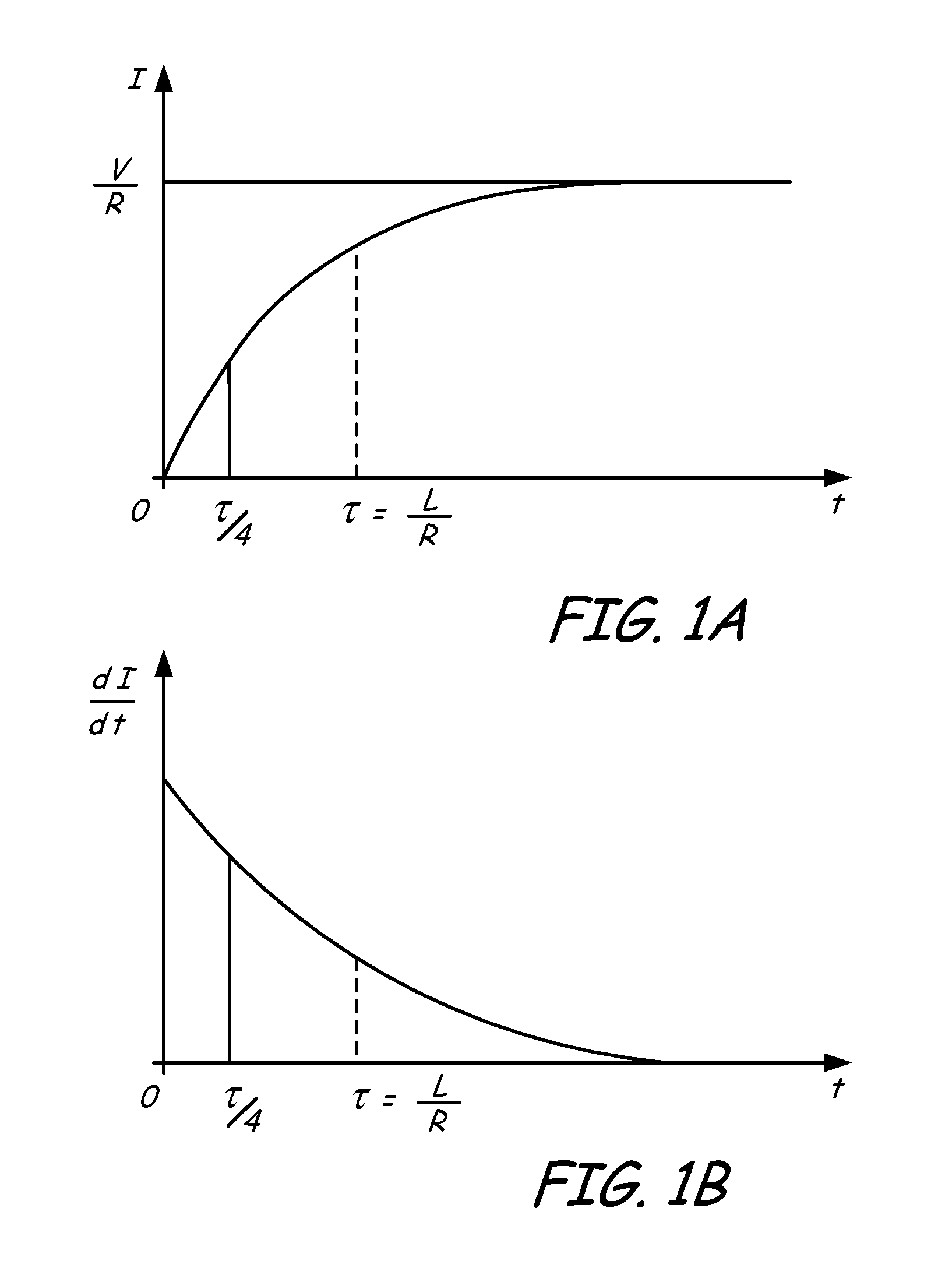
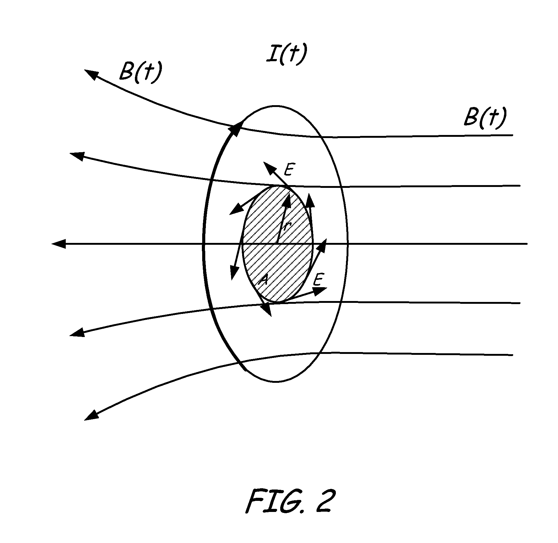
A useful understanding of the properties of the curly electric field generated by an electromagnetic coil can be achieved from an analytical expression for the electric current through the coil as a function of time and analysis of the distribution of the electric field in and around the coil.

For a coil with inductance L and resistance R connected to a DC power supply with voltage U the current through the coil is described by a known function of time:

I(t)=U / R(1−exp(−t / τ))  (1)

Where τ=L / R—is so called a relaxation time of a RL circui...


PUM


Abstract

A method, apparatus and a system for thermally-assisted pulsed electromagnetic field stimulation for treatment of osteoarthritis are disclosed. In one embodiment, the system comprises a multi-coil applicator adapted for positioning near or around of the treated joint, a pulse generator functionally coupled to the applicator, a power supply, and a feedback loop for stabilizing the temperature of the joint. The feedback loop includes a heating element, a temperature sensor and an electronic controller for maintaining the temperature of the joint in the range of 38 to 42 degree C. At elevated temperatures the healing effect of PEMF stimulation on the cartilage is maximized and overall efficiency of the treatment is improved. To produce a high electric field, the coils of the applicator are made with a low number of turns, for example less than 5 turns, and are spatially arranged to cover the whole joint without “dead” zones.

Description

FIELDThe invention relates to a method and apparatus for treatment of osteoarthritis. More particularly, the invention relates to an apparatus for producing pulsed electromagnetic field in arthritic joints, and a method for treating osteoarthritis utilizing pulsed electromagnetic fields.BACKGROUNDOsteoarthritis (OA), sometimes called degenerative joint disease, is a chronic disorder associated with damage to the articular cartilage and surrounding tissues and characterized by pain, stiffness and loss of function. OA commonly affects the hands, spine, and large weight-bearing joints, such as the hips and knees. OA affects nearly 21 million people in the United States, accounting for 25% of visits to primary care physicians. 80% of US population have radiographic evidence of OA by age 65, and 60% of those are symptomatic. In the United States, hospitalizations for osteoarthritis soared from 322,000 in 1993 to 735,000 in 2006.Articular cartilage is the smooth white tissue that covers t...

Claims


Application Information

Patent Timeline
IPC IPC(8): A61N2/04
CPCA61N1/40A61N2/02A61N2/004
Inventor CHORNENKY, VICTORJAAFAR, ALI
Owner BIOMAGNETIC SCI LLC
Why Eureka
Try Eureka