
Anisotropic rare earth-iron based resin bonded magnet

a rare earthiron and resin bonding technology, applied in the field of rare earthiron based resin bonding magnets, can solve the problems of insufficient pressureless sintering of magnetically isotropic strips, insufficient co supply stability, and inability to catch up with the enhancing performance of electric and electronic equipment, so as to achieve effective secure magnetic stability, the effect of squareness of demagnetization curve and not deterioration

Inactive Publication Date: 2011-03-31
MINEBEAMITSUMI INC
View PDF2 Cites 29 Cited by
  • Summary
  • Abstract
  • Description
  • Claims
  • Application Information

AI Technical Summary

Benefits of technology

[0035]The present invention has been made in view of the circumstances described above, and it is an object of the present invention to provide an anisotropic rare earth-iron based resin bonded magnet that can be a next generation type for isotropic Nd2Fe14B based resin bonded magnets with (BH)max of 80 kJ / m3, contributing to miniaturization and a high mechanical output power of rotary machines.
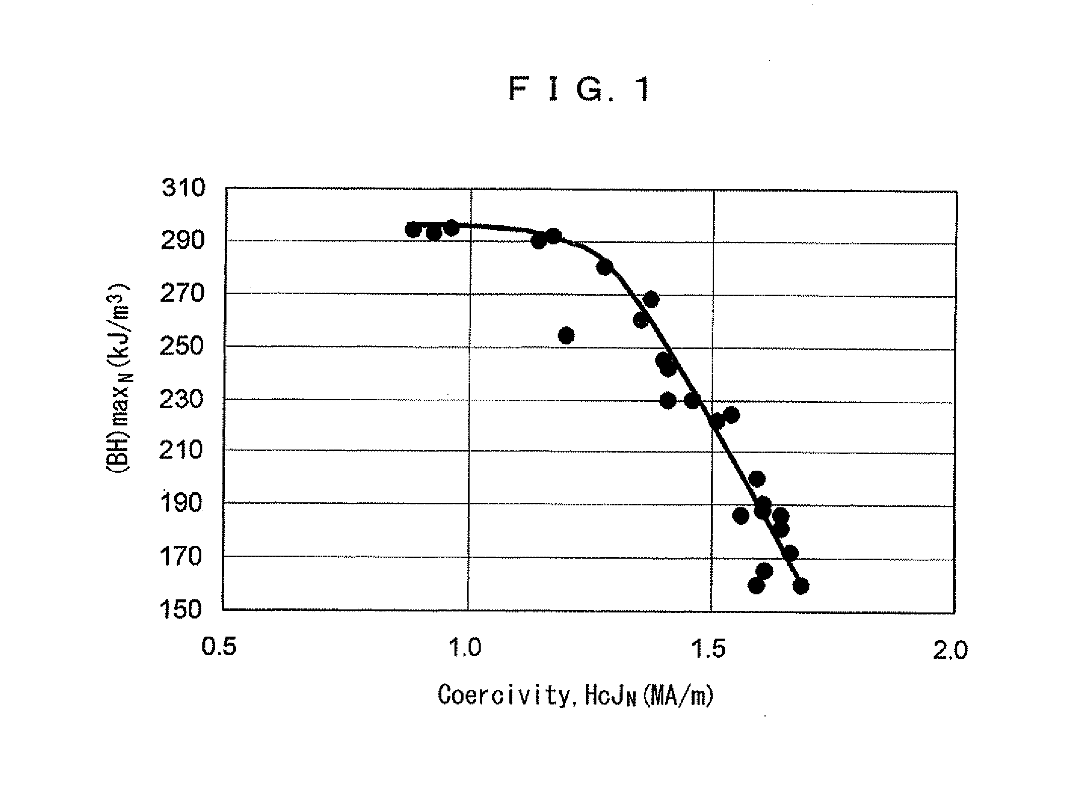
[0041]In an anisotropic rare earth-iron based resin bonded magnet according to the present invention, for improving magnetic stability such as irreversible demagnetization or demagnetizing proof stress against reverse magnetic fields at a high temperature, and magnetic properties typically defined by a (BH)max, the following conditions should be established. When the coercivity of Sm2Fe17N3 based magnetic materials is set to HcJpS, the coercivity of Nd2Fe14B based magnetic materials at a room temperature is set to HcJpN, and a ratio between HcJpS and HcJpN (HcJpS / HcJpN) is set to α, HcJpN is 1 to 1.25 MA / m, and HcJpS is equal to or less than HcJpN (HcJpS<HcJpN). Further, a should be 0.75 or less, or more preferably 0.65 or less.
[0045]As discussed hereinabove, the anisotropic rare earth-iron based resin bonded magnet according to the present invention can be structured as that the squareness of the demagnetization curve at a high temperature based on Hk / HcJRT<Hk / HcJ100 is not deteriorated. Further, since the anisotropic rare earth-iron based resin bonded magnet according to the present invention also has high magnetic properties where the maximum energy product (BH)max is 170, or more than 180 kJ / m3, it would be applicable as the next generation type of an isotropic Nd2Fe14B based resin bonded magnet with a (BH)max of 80 kJ / m3, contributing to make the rotary machines to be further miniaturized and to have higher mechanical output.
[0052]As discussed hereinabove, in an anisotropic rare earth-iron based resin bonded magnet according to the present invention, when the coercivity HcJ at a room temperature is approximately 1 MA / m or more, the squareness at a room temperature is Hk / HcJRT, and the squareness at a temperature of 100° C. is Hk / HcJ100, Hk / HcJRT will be less than Hk / HcJ100 (Hk / HcJRT<Hk / HcJ100). Accordingly, the squareness of demagnetization curve will not be deteriorated at a high temperature, magnetic stability can be well secured, and the maximum energy product (BH)max can be 170 kJ / m3 or more. Here, when considering rotary machines (meaning a magnetic circuit structure between an iron core and a magnet) that can effectively secure the magnetic stability and can employ the air-gap magnetic flux density of the anisotropic rare earth-iron based resin bonded magnet according to the present invention, it is preferable that permeance coefficient Pc is 3 or more.

Problems solved by technology

However, it is not easy to apply the pressureless sintering to magnetic materials while maintaining their magnetic properties in a metastable condition.
Thus, it is obvious that just improving the magnetic properties of magnetically isotropic strips through the rapid solidification method is no longer enough for catching up with the enhancing performance of electric and electronic equipment.
However, the application of Co has problems in its stable supply due to a fragile resource balance and so on.
It would be thus not suitable to apply Co as general-purpose industrial materials.
However, only a limited HcJ is obtainable even if the ingots of Nd2Fe14B based alloy or sintering magnets are milled.

Method used


Image

  • Anisotropic rare earth-iron based resin bonded magnet
  • Anisotropic rare earth-iron based resin bonded magnet
  • Anisotropic rare earth-iron based resin bonded magnet

Examples


embodiments

[0098]Hereinafter, the present invention will be explained in further details based on embodiments. The present invention is not however limited to the embodiments.

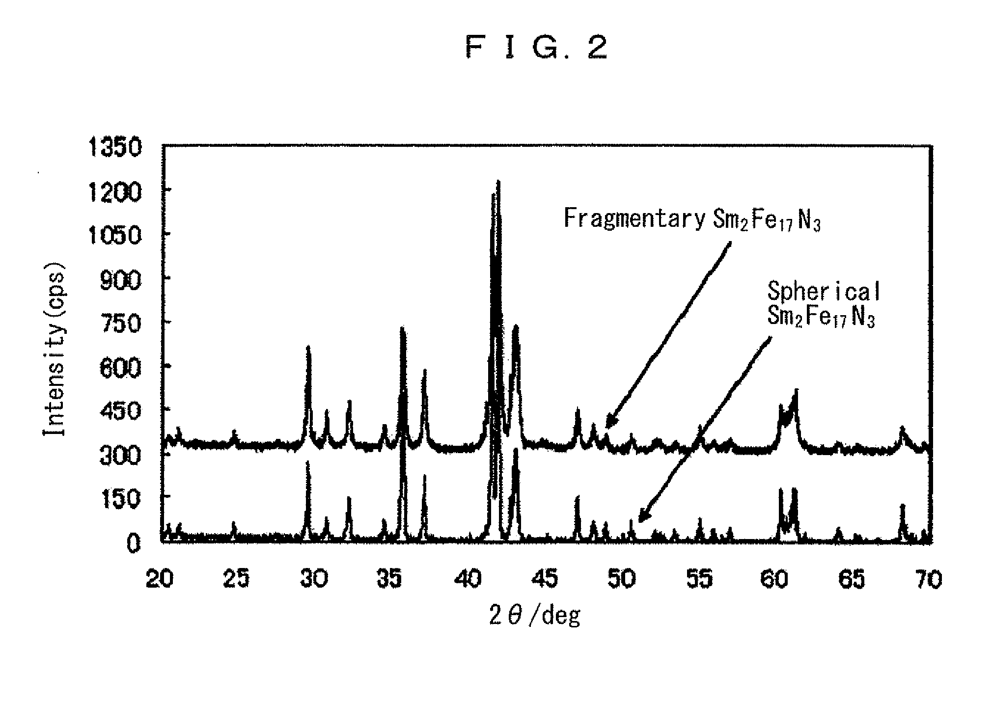
[0099]FIG. 2 is a chart indicating X-ray diffraction patterns of Sm2Fe17N3 based magnetic materials produced without conducting mechanical milling following nitriding of an Sm—Fe alloy, and a fragmentary Sm2Fe17N3 based magnetic material that has been milled through a jet mill following nitriding. As shown, there is no difference in both crystal structures based on a Sm2Fe17N3 intermetallic compound.

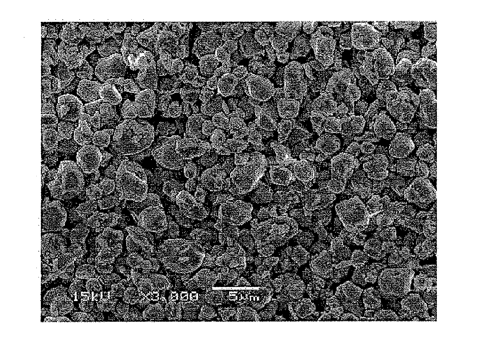
[0100]FIGS. 3A and 3B are SEM (Scanning Electron Microscope) photos indicating two kinds of magnetic materials. Considering the fragmentary Sm2Fe17N3 based magnetic materials as shown in FIG. 3B, it is possible to observe the aggregation of micronized powder formed by milling, the micronized powder having a particle size of less than 1 μm (exclusive). On the other hand, as shown in FIG. 3A, the Sm2Fe17N3 based magnetic materia...


PUM

PropertyMeasurementUnit
Temperatureaaaaaaaaaa
Lengthaaaaaaaaaa
Lengthaaaaaaaaaa

Abstract

Anisotropic rare earth-iron based resin bonded magnet comprises: [1] a continuous phase including: (1) a spherical Sm2Fe17N3 based magnetic material covered with epoxy oligomer where its average particle size is 1 to 10 μm, its average aspect ratio ARave is 0.8 or more, and mechanical milling is not applied after Sm—Fe alloy is nitrided; (2) a linear polymer with active hydrogen group reacting to the oligomer; and (3) additive; and [2] a discontinuous phase being an Nd2Fe14B based magnetic material coated with the epoxy oligomer where its average particle size is 50 to 150 μm, and its average aspect ratio ARave is 0.65 or more, further satisfying: [3] the air-gap ratio of a granular compound on the phases is 5% or less; and [4] a composition where crosslinking agent with 10 μm or less is adhered on the granular compound is formed at 50 MPa or less.

Description

BACKGROUND OF THE INVENTION[0001]1. Field of the Invention[0002]The present invention relates to a rare earth-iron based resin bonded magnet, and more particularly to an anisotropic rare earth-iron based resin bonded magnet with high magnetic properties that will satisfy the following conditions: when coercivity HcJ at a room temperature is approximately 1 MA / m, a squareness at a room temperature is Hk / HcJRT, and a squareness at a temperature of 100° C. is Hk / HcJ100, Expression Hk / HcJRT<k / HcJ100 is obtainable. In this anisotropic rare earth-iron based resin bonded magnet, squareness deterioration based on a demagnetization curve at a high temperature can be avoided, and the maximum energy product (BH)max can be 170 kJ / m3 or more.[0003]2. Description of the Related Art[0004]Material types for rare earth-iron based magnet such as Nd2Fe14B base, αFe / Nd2Fe14B base and Fe3B / Nd2Fe14B base that are obtainable through rapid solidification, for example, a melt spinning method, are limited...

Claims


Application Information

Patent Timeline
IPC IPC(8): H01F7/02
CPCH01F1/0578H01F1/059H01F41/028H01F41/0266H01F7/02
Inventor YAMASHITA, FUMITOSHIYAMADA, OSAMUOHYA, SHIHO
Owner MINEBEAMITSUMI INC
Learn More