
Wireless transmission system, wireless communication device and wireless transmission method

a wireless communication and wireless transmission technology, applied in multi-frequency code systems, diversity/multi-antenna systems, multi-frequency communication, etc., can solve problems such as increased power consumption, increased an influence of signal distortion, and increased unnecessary radiation and so on

Inactive Publication Date: 2011-03-31
SONY CORP
View PDF8 Cites 28 Cited by
  • Summary
  • Abstract
  • Description
  • Claims
  • Application Information

AI Technical Summary

Benefits of technology

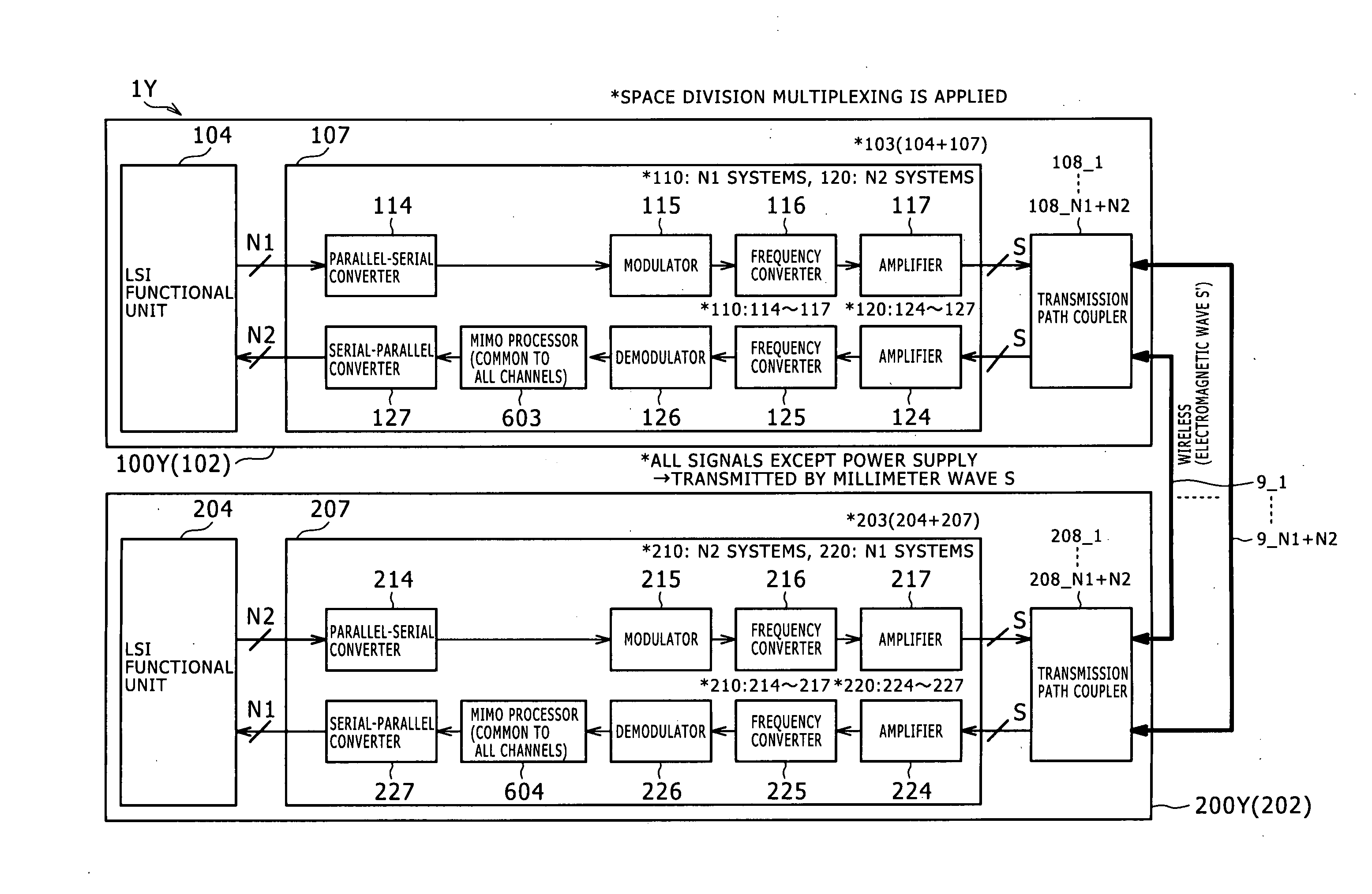
[0021]With the embodiment of the present invention, a mechanism suitable for wireless signal transmission between different apparatus or within an apparatus wherein the MIMO process is applied on the reception side is implemented without using the OFDM modulation method together. By applying the MIMO process to the reception side, the antenna distance can be reduced.
[0022]Since both of a desired wave and an unnecessary wave are handled as direct waves, it becomes possible to manage the path difference regarding the desired wave and the unnecessary wave and it becomes possible to determine the antenna arrangement so as to be convenient for the MIMO process on the reception side. Particularly, the antenna arrangement is determined taking it into consideration that demodulation is carried out by envelope detection or square-law detection. As a result, in comparison with an alternative case wherein the present invention is not applied, the calculation scale of the MIMO process can be reduced.
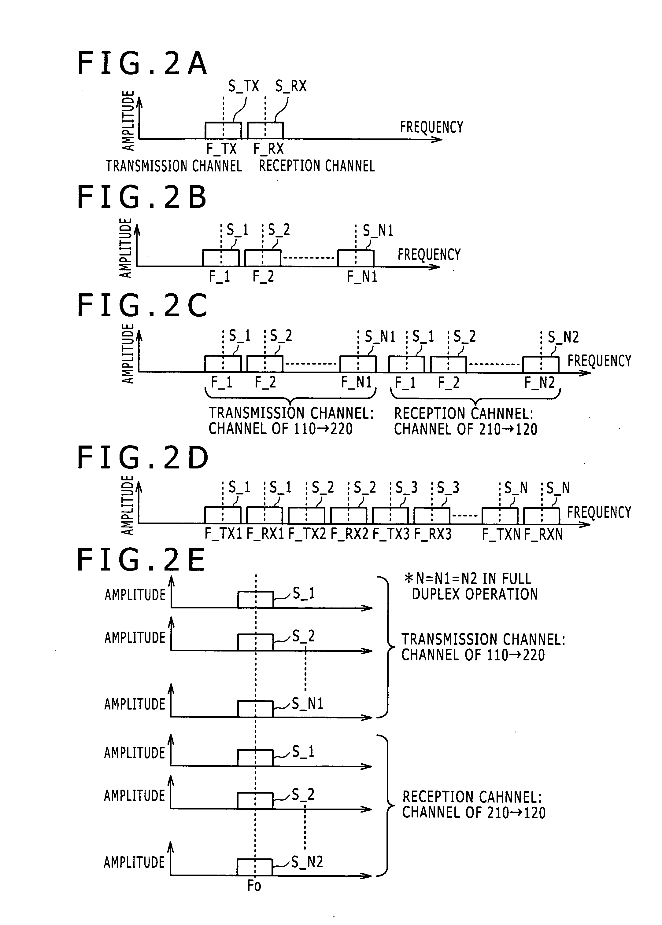
[0023]Preferably, the carrier signals used for the modulation and the demodulation use a common frequency. Where the common frequency is used in this manner, since the influence of the carrier frequency becomes same among the different channels with certainty. Therefore, the MIMO process in the baseband region can be carried out with certainty and efficiently. In addition, the circuit scale for modulation and demodulation can be reduced in comparison with that in an alternative case wherein the carrier frequencies of the channels are different from each other.

Problems solved by technology

However, together with further increase of the amount of transmission information and further increase of the speed of transmission recently, increase of power consumption, increase of an influence of signal distortion by reflection and so forth, increase of unnecessary radiation and so forth have become problems.
However, the countermeasure just described gives rise to increase of the number of input and output terminals.
As a result, complication of a printed board or a cable wiring scheme, increase of the size of a semiconductor chip and so forth are required.
Further, since a large amount of data is transmitted at a high speed along a wiring system, a problem of electromagnetic field interference occurs.
All of the problems involved in the LVDS or the technique of increasing the number of wiring lines are caused by transmission of a signal through an electric wiring line.
However, where the space division multiplexing is applied, an interference countermeasure between channels is required.

Method used


Image

  • Wireless transmission system, wireless communication device and wireless transmission method
  • Wireless transmission system, wireless communication device and wireless transmission method
  • Wireless transmission system, wireless communication device and wireless transmission method

Examples


first embodiment

[0292]Therefore, where inaccuracy or nonlinearity cannot be accepted, a MIMO process should be used in combination with an envelope detection output. However, where inaccuracy can be accepted, it is possible to use a MIMO process in combination with the square-law detection and the configuration of the first embodiment shown in FIG. 14 will be adopted.

second embodiment

[0293]On the other hand, where “n” is an odd number, since the average value of the composite signal is low, a MIMO process is preferably combined with the envelope detection, and since it is actually difficult to adopt a combination of a MIMO process with the square-low detection, the configuration of the second embodiment shown in FIG. 19 will be adopted.

[0294]Here, as can be supposed from FIGS. 10A to 100, the magnitude of the average level of the received composite signal is influenced by whether n is an even number or an odd number. Specifically, where n is an even number as seen in FIG. 21A, since the real number term or cos term is in the positive as seen in FIG. 10B, that is, there is no phase delay and the phase is same, a desired phase and an unnecessary wave appear in the same phase. Therefore, the effective carrier signal component of the ASK increases. In other words, the average value of the composite signal received by the antenna 236 on the reception side increases c...


PUM


Abstract

Disclosed herein is a wireless transmission system. Transmission antennas are provided on a first communication apparatus while reception antennas individually corresponding to the transmission antennas are provided on a corresponding second communication apparatus. Each reception antenna receives a desired wave from a corresponding transmission antenna as a direct wave and receives an unnecessary wave from a different transmission antenna as a direct wave. The first communication apparatus modulates only the amplitude of a carrier signal for all channels. The second communication apparatus demodulates composite waves of desired waves and unnecessary waves received by the reception antennas by envelope detection or square-law detection and carries out correction operation for the demodulation signals based on transmission characteristics of transmission spaces between the transmission and reception antennas to acquire transmission subject signals.

Description

BACKGROUND OF THE INVENTION[0001]1. Field of the Invention[0002]This invention relates to a wireless transmission system (including also a wireless communication device implemented in one housing), a wireless communication device for the reception side and a wireless communication method. More particularly, the present invention relates to a mechanism wherein space division multiplexing is applied to wirelessly transmit a plurality of transmission subject signals.[0003]2. Description of the Related Art[0004]As a technique for implementing a high-speed signal transmission between different electronic apparatus disposed in a comparatively short range (for example, within several centimeters to ten and several centimeters), or within an electronic apparatus, for example, a LVDS (Low Voltage Differential Signaling) is known. However, together with further increase of the amount of transmission information and further increase of the speed of transmission recently, increase of power cons...

Claims


Application Information

Patent Timeline
Patent Type & Authority Applications(United States)
IPC IPC(8): H04K1/10H04B7/04H04J99/00
CPCH04B7/04H04B7/0413
Inventor MIHOTA, NORIHITO
Owner SONY CORP
Learn More