Liquid material vaporizer and film deposition apparatus using the same

Inactive Publication Date: 2011-04-07
TOKYO ELECTRON LTD
View PDF3 Cites 4 Cited by
  • Summary
  • Abstract
  • Description
  • Claims
  • Application Information

AI Technical Summary

Benefits of technology

[0038]According to the present invention, the material gas generated by the first liquid material vaporizer can be spouted toward the inside surface of the mist trap member of the second liquid material vaporizer that is uniformly heated as a whole. Thus, it is possibl

Problems solved by technology

The droplet, which has passed through the vaporizing surface without being vaporized, flows into the film deposition chamber with the flow of the carrier gas, resulting in generation of particles.
These particles may adhere to a substrate, which invites abnormal film deposition and/or give an adverse effect on a film quality.
However, since the breathable member, such as a solid filler or a porous body, which has been conventionally used for vaporizing droplets of the liquid material, is heated by the heat conducted from an end of the breathable member to the whole thereof, the heat cannot be uniformly supplied to the breathable member.
In this area, the droplets may not be fully vaporized, resulting in clogging.
In this case, the area to which the heat is difficult to be transmitted is not sufficiently replenished with a thermal energy corresponding to the vaporization heat.
As a result, there is generated a temperature difference in the breathable member.
In this case, the temperature of a certain area of the breathable member may not reach a temperature at which a liquid material can be vaporized, whereby the liquid material

Method used


Image

  • Liquid material vaporizer and film deposition apparatus using the same
  • Liquid material vaporizer and film deposition apparatus using the same
  • Liquid material vaporizer and film deposition apparatus using the same

Examples


first embodiment

Film Deposition Apparatus in First Embodiment

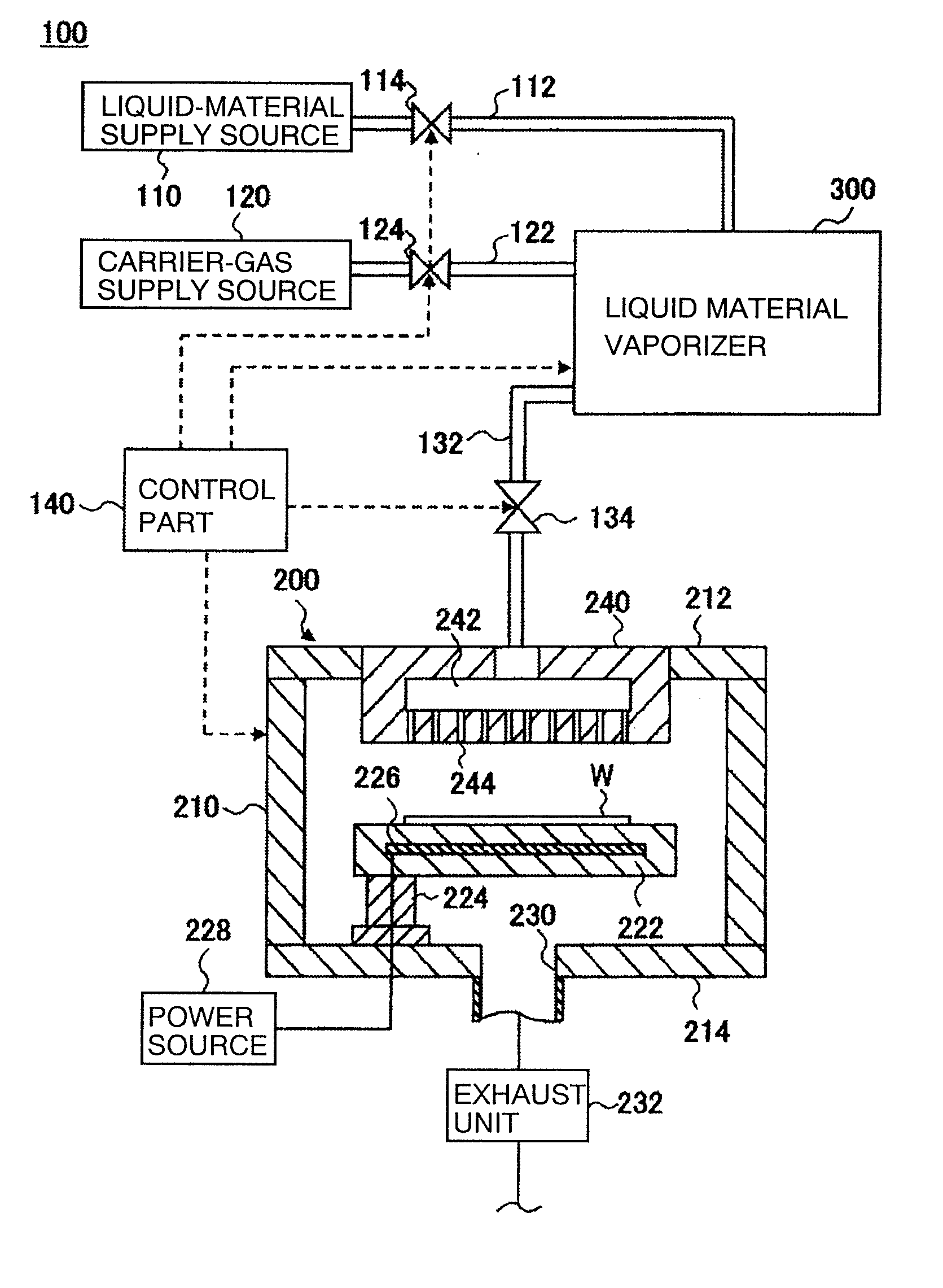
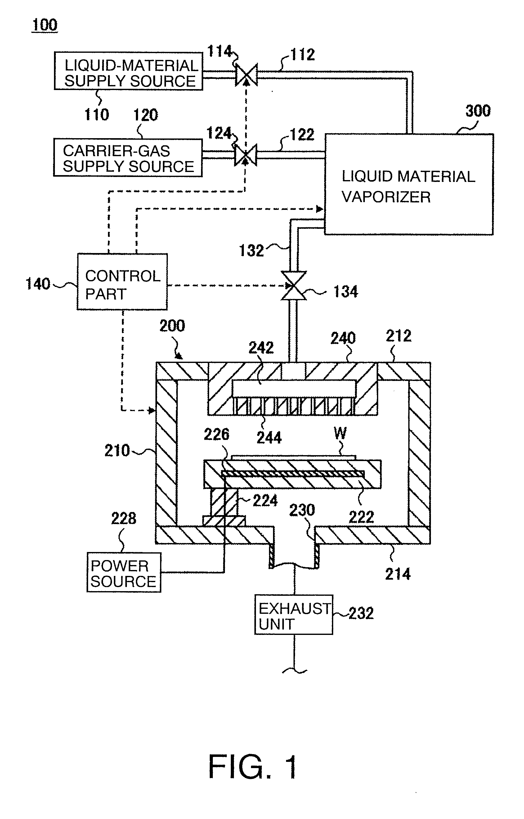
[0053]A film deposition apparatus in a first embodiment according to the present invention is firstly described with reference to the drawings. FIG. 1 is a view for explaining a schematic structural example of the film deposition apparatus in the first embodiment. The film deposition apparatus 100 shown in FIG. 1 is configured to deposit a metal oxide film on a substrate to be processed, such as a semiconductor wafer (hereinafter referred to simply as “wafer”) W, by a CVD method. For example, the film deposition apparatus 100 includes: a liquid-material supply source 110 configured to supply a liquid material containing Hf such as HTB (hafnium tertiary butoxide); a carrier-gas supply source 120 configured to supply an inert gas such as Ar as a carrier gas; a liquid material vaporizer 300 configured to vaporize the liquid material supplied from the liquid-material supply source 110 so as to generate a source gas; a film deposition chamber ...

second embodiment

Film Deposition Apparatus in Second Embodiment

[0125]Next, the film deposition apparatus in a second embodiment according to the present invention is described with reference to the drawings. FIG. 11 is a view for explaining a schematic structural example of the film deposition apparatus 102 in the second embodiment. In the film deposition apparatus 102 shown in FIG. 11, the liquid material vaporizer 300 shown in FIG. 1 is replaced with a liquid material vaporizer 302. In FIG. 11, the components other than the liquid material vaporizer 302 are the same as those of the film deposition apparatus shown in FIG. 1. Thus, in FIG. 11, the components having the same functions and structures as those shown in FIG. 1 are shown by the same reference numbers, and detailed description thereof is omitted.

[0126]The liquid material vaporizer 302 shown in FIG. 11 includes: a first liquid material vaporizer 304 configured to vaporize the liquid material supplied from the liquid-material supply source ...


PUM

PropertyMeasurementUnit
Thicknessaaaaaaaaaa

Abstract

The present invention is a liquid material vaporizer comprising a liquid-material supply part configured to make a liquid material into a droplet state and to discharge the same, and a vaporizing part configured to vaporize the liquid material in a droplet state so as to generate a source gas, the vaporizing part including: an inlet port to which the liquid material in a droplet state is introduced from the liquid-material supply part; a housing body of a bottomed tubular shape, the housing body having an opening end on a side of the inlet port; a columnar block having a flange for closing the opening end of the housing body, the columnar block being fitted in the housing body in such a manner that a gap serving as a vaporizing path is defined between the columnar block and an inside surface of the housing body; a breathable mist trap member disposed in the vaporizing path formed between the inside surface of the housing body and an outside surface of the columnar block, in such a manner that the mist trap member is in contact with the inside surface of the housing body and covers the outside surface of the columnar block; a heating part disposed to cover the housing body, the heating part being configured to heat the mist trap member through the housing body; a spout formed in the columnar block in such a manner that the spout is in communication with the inlet port, and passes through the columnar block from an end surface of the columnar block on the side of the inlet port to a side surface of the columnar block, the spout being configured to spout the liquid material in a droplet state, which has been introduced from the inlet port, toward an inside surface of the mist trap member; and an outlet port disposed in a bottom part of the housing body, the outlet port being configured to deliver a source gas generated by the mist trap member that vaporizes the liquid material in a droplet state in the vaporizing path.

Description

FIELD OF THE INVENTION[0001]The present invention relates to a liquid material vaporizer configured to vaporize a liquid material so as to generate a source gas, and a film deposition apparatus using the same.BACKGROUND ART[0002]As a method of depositing a dielectric film, a metal film, or a semiconductor film, on a surface of a substrate to be processed such as a semiconductor substrate or a glass substrate, a chemical vapor deposition (CVD) method is known in which an organic source gas such as an organic metal compound is supplied to a film deposition chamber in which the substrate to be processed is placed, and the organic source gas is reacted with another gas such as oxygen or ammonia so as to deposit a film. An organic material used in such a CVD method is generally liquid or solid at normal temperatures. Thus, a vaporizer for vaporizing the organic material is needed.[0003]Generally, the organic material is previously liquidized into a liquid material by means of a solvent, ...

Claims


Application Information

Patent Timeline
IPC IPC(8): C23C16/455B05B1/24
CPCC23C16/4486C23C16/405
Inventor OKURA, SHIGEYUKI
Owner TOKYO ELECTRON LTD
Why Eureka
Try Eureka