Hybrid energy storage system

a technology of energy storage system and hybrid battery, which is applied in the direction of secondary cell servicing/maintenance, capacitor propulsion, etc., can solve the problems of difficult thermal management of the battery, the power density of the most available battery is relatively low, and the design of energy storage system for applications is difficult. to achieve the effect of prolonging the life of the power sour

Active Publication Date: 2011-04-14
TURNTIDE TECH INC
View PDF8 Cites 69 Cited by
  • Summary
  • Abstract
  • Description
  • Claims
  • Application Information

AI Technical Summary

Benefits of technology

In the controlled charging mode, energy generated by the application is preferably directed to charge the ultra-capacitor. In one embodiment, only when the ultra-capacitor is fully charged is the generated energy directed to the power source. The controlled charging mode can thus isolate the power source from random charges, which can desirably extend the life of the power source.

Problems solved by technology

These applications typically have fluctuating load profiles that present challenges in the design of energy storage systems for the applications.
However, using batteries as the sole energy source has several disadvantages.
Unfortunately, most available batteries have a relatively low power density.
Although there are high power density batteries available, their price is typically much higher than low power density batteries and with the increased power density, thermal management of the battery becomes a challenge.
In advanced automotive applications, because the load profile varies rapidly according to the road conditions and the driver's behavior, the energy storage system suffers from random charges (e.g. regenerative braking) and discharges (e.g. accelerating), which have a negative effect on the life of the battery.
Balancing of a voltage of each cell in a battery system is another problem concerning the battery because, without a balancing system, individual cell voltages will drift apart over time and the voltage capacity of the total pack will decrease quickly during operation, which can result in the failure of the entire battery system.
This condition is especially severe when the battery has a long string of cells or the battery is used to do frequent high rate charges and discharges.
However, this configuration also has disadvantages.
For example, the energy generated by an application, such as regenerative braking, cannot be effectively controlled to be absorbed by the ultra-capacitor and instead the generated energy is directed to the battery, thereby shortening the life of the battery.
A large bi-directional DC / DC converter can be expensive and has thermal management issues that must be addressed.
However, this configuration limits the working range of the ultra-capacitor.
Disadvantages of this configuration include additional expense for a second converter and reliability issues.
A disadvantage of this configuration is that two converters are required.

Method used


Image

  • Hybrid energy storage system
  • Hybrid energy storage system
  • Hybrid energy storage system

Examples


Embodiment Construction

This invention includes a hybrid energy storage system that can be electrically connected to and used to supply power to a variety of applications including, but not limited to, electric vehicles, hybrid electric vehicles, plug-in hybrid electric vehicles, non-propulsion loads in vehicles, robotic applications, active power filters, wind energy harvesting equipment and solar energy harvesting equipment. For purposes of explanation herein, portions of the description below will be directed to the hybrid energy storage system applied to electric vehicles. This focus is not intended to limit this invention to such applications.

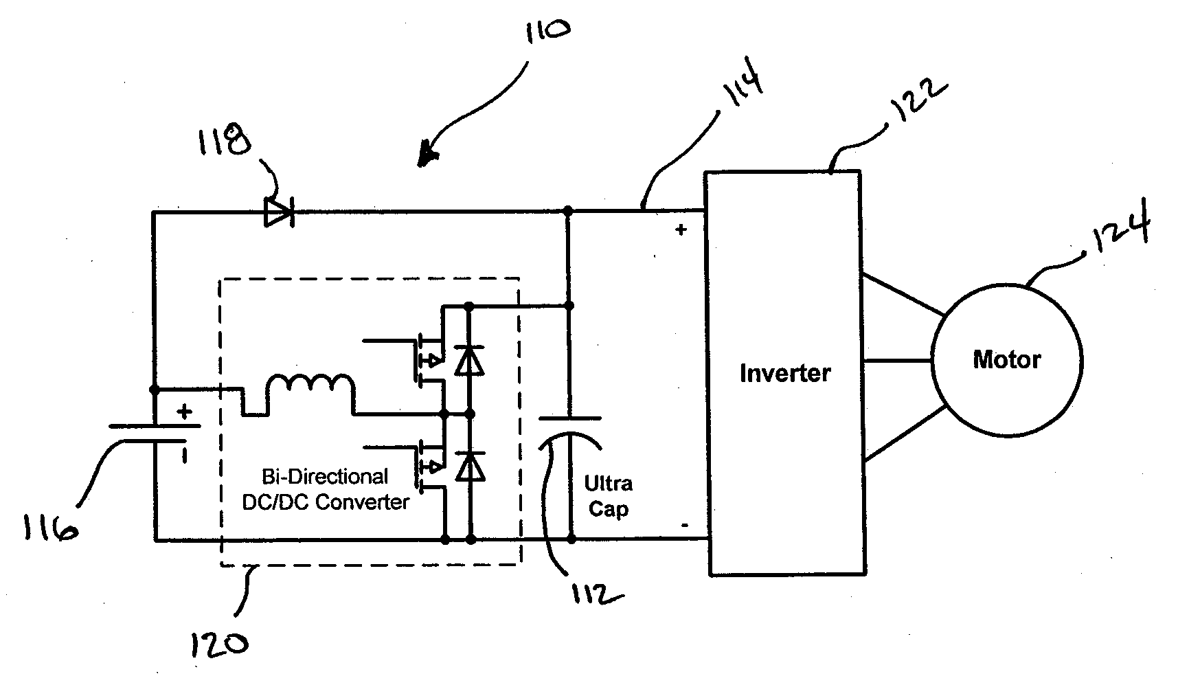
FIG. 5 shows a circuit diagram of a hybrid energy storage system 10 according to one embodiment of this invention. Hybrid energy storage system 10 includes an ultra-capacitor12 electrically connected to a DC bus 14 and a power source 16 is electrically connected to the DC bus 14 via a switch 18. The ultra-capacitor 12 and the power source 16 are connected via a D...


PUM


Abstract

A hybrid energy storage system for supplying power to an application with a fluctuating load profile, such as, for example, electric vehicles, hybrid electric vehicles, plug-in hybrid electric vehicles, wind energy harvesting equipment and solar energy harvesting equipment. The hybrid energy storage system includes an ultra-capacitor electrically connected to a DC bus and a power source electrically connected to the DC bus via a controlled switch. The hybrid energy storage system further including a DC / DC converter connected between the power source and the ultra-capacitor, the DC / DC converter boosting a voltage of the power source to charge the ultra-capacitor. The DC / DC converter is preferably controlled to maintain a voltage of the ultra-capacitor at a higher value than the voltage of the power source.

Description

BACKGROUND OF THE INVENTION1. Field of the InventionThis invention is directed to a hybrid energy storage system for supplying power to an application with a fluctuating load profile, such as, for example, electric vehicles, hybrid electric vehicles, plug-in hybrid electric vehicles, wind energy harvesting equipment and solar energy harvesting equipment.2. Discussion of Related ArtRecently there has been an increasing interest in environmentally friendly applications such as, electric vehicles, hybrid electric vehicles, plug-in hybrid electric vehicles, wind energy harvesting equipment, and solar energy harvesting equipment. These applications typically have fluctuating load profiles that present challenges in the design of energy storage systems for the applications. Conventional approaches for powering these applications have various shortcomings.Batteries are commonly used for energy storage in the above described applications. However, using batteries as the sole energy source h...

Claims


Application Information

Patent Timeline
Patent Type & Authority Applications(United States)
IPC IPC(8): H02J7/00
CPCH01M10/44Y02T90/127H01M2220/20Y02E60/12B60L7/14B60L11/005B60L11/1803B60L11/1816B60L11/1866B60L11/1887B60L2210/10B60L2240/12B60L2240/547B60L2240/549Y02T10/7022Y02T10/7094Y02T10/7061Y02T10/7216Y02T90/34Y02T90/14H01M2220/10B60L50/40B60L50/51B60L53/14B60L58/22B60L58/40Y02E60/10Y02T10/70Y02T10/7072Y02T10/72Y02T90/12Y02T90/40
Inventor CAO, JIANEMADI, ALI
Owner TURNTIDE TECH INC
Why Eureka
Try Eureka