Ultrasound Guided Probe Device and Sterilizable Shield for Same

a technology of ultrasound guided probes and shields, which is applied in the field of ultrasound guided probe devices and sterilizable shields for same, can solve the problems of no simple nor risk-free procedure, delay in delivery of life-saving fluids or medications, and risk of unsuccessful placement of probes

Active Publication Date: 2011-04-14
SOMA RES LLC
View PDF74 Cites 71 Cited by
  • Summary
  • Abstract
  • Description
  • Claims
  • Application Information

AI Technical Summary

Benefits of technology

Disclosed in one embodiment is a medical probe device. The skin contacting surface can include a first portion and a second portion that are angled with respect to one another. More specifically, the first portion can define a first plane and the second portion can define a second plane, and these two planes can intersect one another to define an angle therebetween that is greater than about 150° and less than 180°. In addition, the first portion of the skin contacting surface can define a probe guide therethrough, and the second portion can be associated with an ultrasound transducer such that an ultrasonic beam transmitted from the ultrasound transducer issues from the second portion. In one embodiment, the first portion of the skin contacting surface can be defined by a first portion of the medical probe device and the second portion of the skin contacting surface can be defined by a second portion of the medical probe device, and the first and second portions of the medical probe device can be removably cooperable with one another.

Problems solved by technology

This is neither a simple nor a risk-free procedure.
Risks of unsuccessful placement of a probe can range from minor complications, such as patient anxiety and discomfort due to repetition of the procedure following incorrect initial placement, to severe complications, such as pneumothorax, arterial or venous laceration, or delay of delivery of life-saving fluids or medications in an emergency situation.
Such techniques are very difficult perceptually.
For instance, these techniques are complicated by the fact that the person targeting the tissue with the probe is not the same person as is operating the ultrasound.
In addition, the generally thin, cylindrical probe is usually small and reflects very little of the ultrasound beam.
Moreover, as the cylindrical probe and the ultrasound beam are not generally normal to one another, the small amount of ultrasonic energy that is reflected from the probe will reflect at an angle to the incident beam, resulting in little if any of the reflected energy being detected by the ultrasound transducer.
As a result, the probe itself is difficult to visualize in the sonogram and the person placing the probe must attempt to guide the probe to the correct location using minimal visual feedback.
For example, the only visual feedback available is often only subtle artifacts of the motion of the probe such as slight changes in the sonogram as the probe deflects and penetrates the surrounding tissue.
Problems still exist with such devices however.
In addition, and as with hand-guided ultrasound techniques, very little, if any, ultrasonic energy is reflected from the probe back to the transducer.
In fact, due to the lack of lateral motion of the probe, visual cues to the location of the probe tip may be even more difficult to discern on a sonogram when using these devices.
In addition, in many of these devices, the probe passes through the ultrasound beam at a fixed depth range depending on the set angle of the probe guide, and this may not correspond to the depth of the target, in which case it may not be possible to show the juncture of the target and the probe tip on the sonogram at all.

Method used


Image

  • Ultrasound Guided Probe Device and Sterilizable Shield for Same
  • Ultrasound Guided Probe Device and Sterilizable Shield for Same
  • Ultrasound Guided Probe Device and Sterilizable Shield for Same

Examples


Embodiment Construction

Reference will now be made in detail to various embodiments of the disclosed subject matter, one or more examples of which are set forth below. Each embodiment is provided by way of explanation of the subject matter, not limitation of the subject matter. In fact, it will be apparent to those skilled in the art that various modifications and variations may be made in the present disclosure without departing from the scope or spirit of the subject matter. For instance, features illustrated or described as part of one embodiment, may be used in another embodiment to yield a still further embodiment. Thus, it is intended that the present disclosure cover such modifications and variations as come within the scope of the appended claims and their equivalents.

Definitions

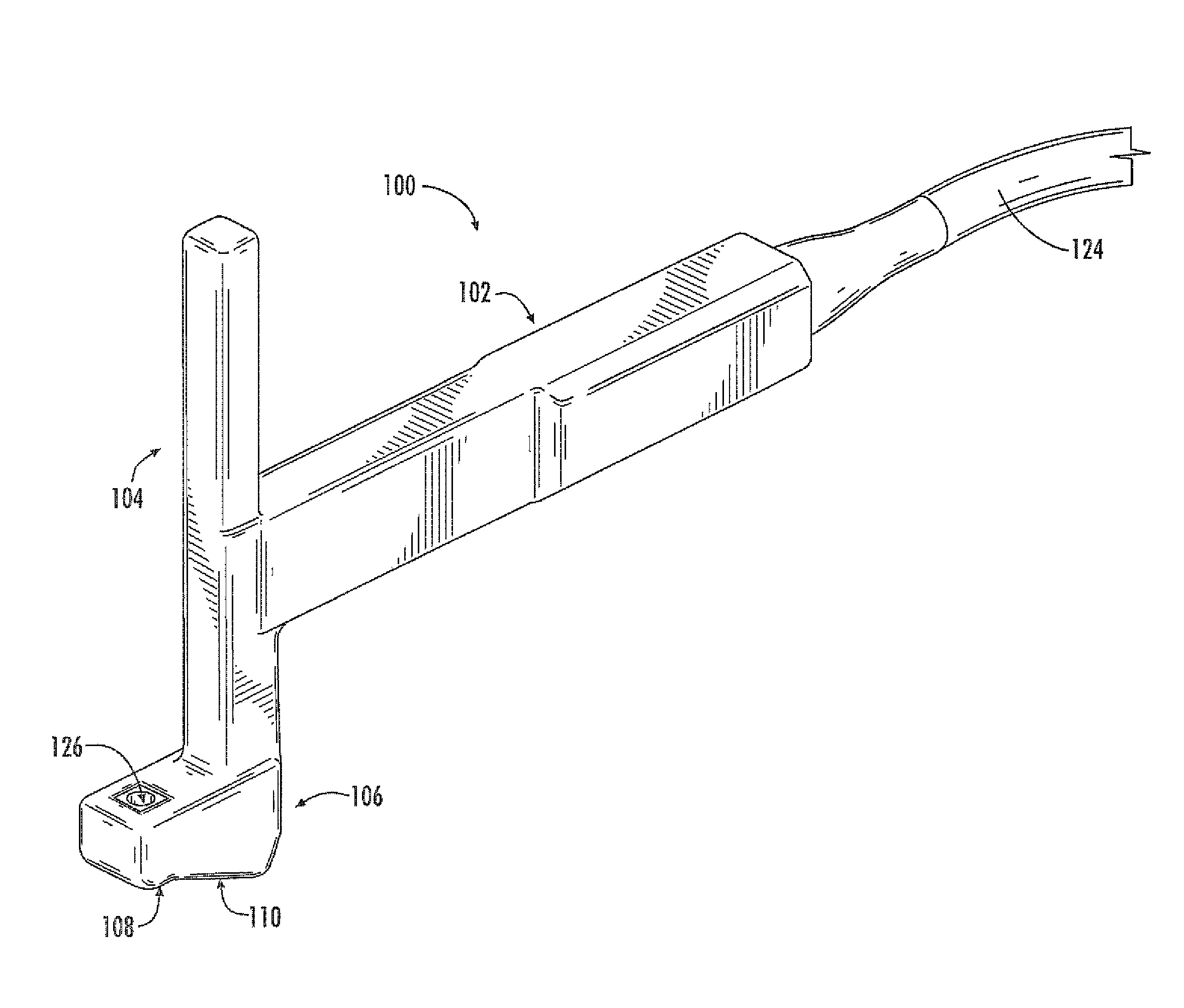
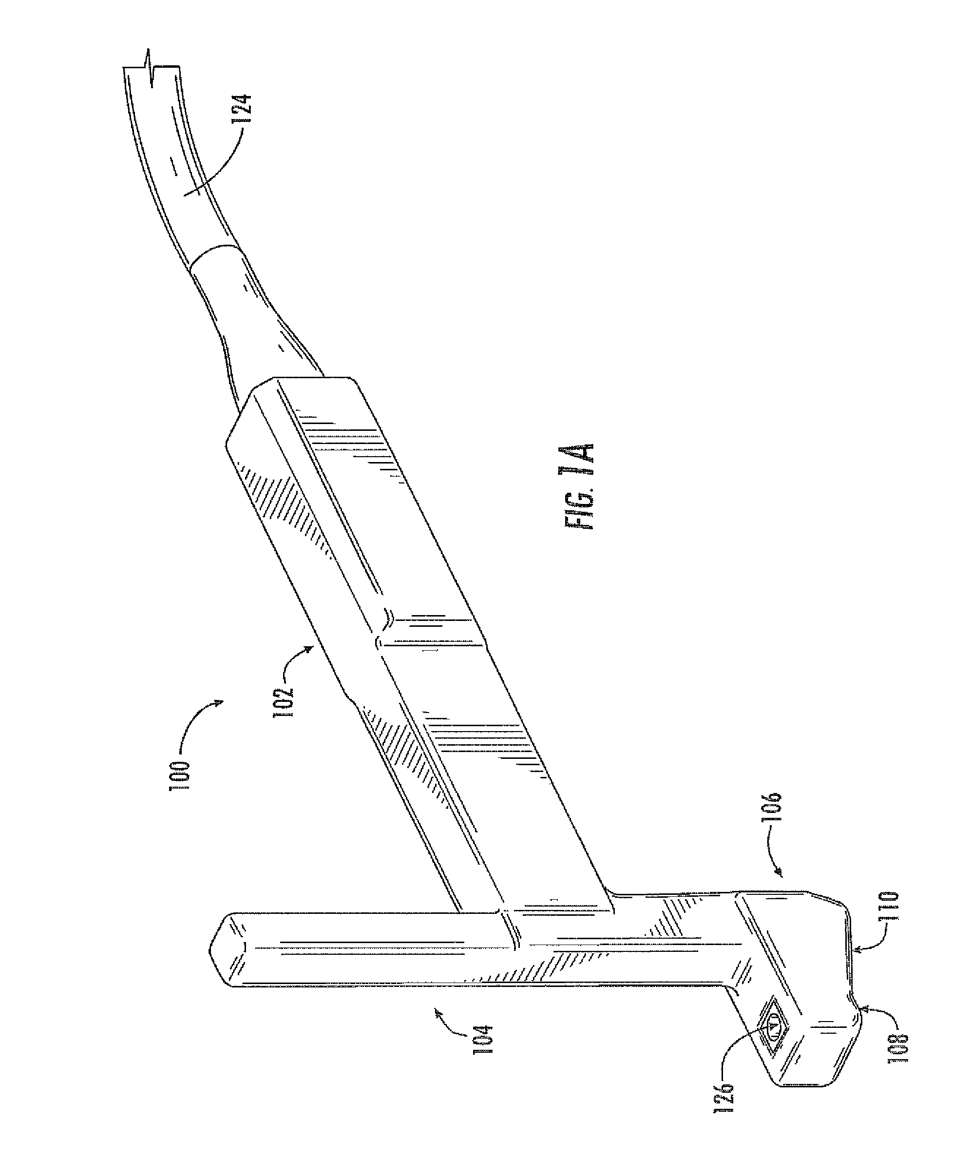
As utilized herein, the term “probe” generally refers to a device that can be guided to a percutaneous location, for instance for delivery of a therapeutic, e.g., a compound or a treatment, to the location; for removal of m...


PUM


Abstract

Disclosed are medical probe devices and methods for use guiding of percutaneous probes during medical procedures. The probe devices include an ultrasound transducer housing having a passage therethrough configured to accommodate a probe. The devices can be utilized to guide a probe through the probe guide to a percutaneous target with real time visualization of the probe during the procedure. In addition, the devices can include a sterilizable shield including a sterile probe guide such that the transducer housing itself can be separated from a subject by a sterile barrier. The sterilizable shield can be a single-use shield that can prevent contamination and re-use of the shield. The devices can define a beneficial geometry conducive to use by a single operator that can be utilized for percutaneous targets near the skin surface and can enable excellent contact between the device and the skin surface of a subject.

Description

BACKGROUND OF THE INVENTIONMedical probe devices are utilized for many purposes, chief of which include catheterization, centesis, and biopsy procedures. Percutaneous placement of probes using these devices is often performed with techniques which rely on ascertaining the correct locations of palpable or visible structures. This is neither a simple nor a risk-free procedure. For instance, proper insertion and placement of a percutaneous probe depends on correct localization of anatomical landmarks, proper positioning of the patient in relation to the care provider, and awareness of both the target's depth and angle from the point of probe insertion. Risks of unsuccessful placement of a probe can range from minor complications, such as patient anxiety and discomfort due to repetition of the procedure following incorrect initial placement, to severe complications, such as pneumothorax, arterial or venous laceration, or delay of delivery of life-saving fluids or medications in an emerg...

Claims


Application Information

Patent Timeline
Patent Type & Authority Applications(United States)
IPC IPC(8): A61B8/14
CPCA61B1/00142A61B8/0833A61B8/0841A61B8/4281A61B17/3403A61B8/461A61B2017/00296A61B2017/00858A61B2017/3405A61B2017/3413A61B8/4254A61B19/081A61B8/4209A61B46/10A61B8/4422
Inventor RIDLEY, STEPHEN F.HAGY, M. DEXTER
Owner SOMA RES LLC
Why Eureka
Try Eureka