Cathode for hydrogen generation and method for producing the same

a cathode and hydrogen generation technology, applied in the direction of electrolyte coatings, cell components, manufacturing tools, etc., can solve the problems of reducing the operation method of the electrolyzer, the reduction of the electrolytic voltage, and the reduction of the energy consumption of the electrolyte, so as to achieve the effect of superior durability and low hydrogen overvoltag

Active Publication Date: 2011-04-21
ASAHI KASEI KK
View PDF13 Cites 6 Cited by
  • Summary
  • Abstract
  • Description
  • Claims
  • Application Information

AI Technical Summary

Benefits of technology

[0029]According to the present invention, a cathode for hydrogen generation which can be used for electrolysis of an aqueous alkali metal compound solution, in particular, a cathode which can be suitably used for a zero gap electrolyzer, and has a low hydrogen overvoltage, superior durability, resistance against the reverse current generated when operation of the electrolyzer is stopped, and resistance against Fe ion included in the electrolytic solution, is provided.

Problems solved by technology

The major problem in electrolysis is reduction of energy consumption, more specifically, reduction in electrolytic voltage.
However, this method of stopping the operation of electrolyzer needs to be improved due to complicated operational procedures and cost increase in ancillary facilities, and the like.
However, it is known that ruthenium oxide is subjected to an oxidative degradation by reverse current, and therefore, it is necessary that the protection current is passed when operation of the electrolyzer is stopped.
However, a cathode for hydrogen generation using only platinum has a problem in durability because platinum physically drops off during electrolysis.
Further, it is also a serious problem that the cathode is easily poisoned by Fe ion included in the electrolytic solution leading to a rise in electrolytic voltage.
However, because of a low degree in crystallinity of iridium oxide and insufficient durability against reverse current, this cathode for hydrogen generation has not been industrialized.
However, a cathode for hydrogen generation having a low hydrogen overvoltage and sufficient durability against the reverse current and Fe impurities in the electrolytic solution, and further resistance against the reverse current when electrolysis is stopped, has not yet been realized.

Method used


Image

  • Cathode for hydrogen generation and method for producing the same
  • Cathode for hydrogen generation and method for producing the same
  • Cathode for hydrogen generation and method for producing the same

Examples


example 1

[0089]As the conductive base material, a woven mesh base material which was made by knitting a nickel fine wire having a diameter of 0.15 mm in a sieve mesh size of 40 was used. The conductive base material was blasted with alumina powder having a weight average particle size of 100 μm or less, then subjected to an acid treatment in 6N hydrochloric acid at room temperature for 5 minutes, followed by rinsing with water and drying.

[0090]Subsequently, an application liquid was prepared by mixing a dinitrodiammineplatinum nitric acid solution (produced by Tanaka Kikinzoku Kogyo K.K., platinum concentration: 100 g / L) and an iridium chloride solution (produced by Tanaka Kikinzoku Kogyo K.K., iridium concentration: 100 g / L) so that a molar ratio of platinum to iridium became 0.27:0.73.

[0091]A vat including the application liquid was placed in the lowest part of the coating roll, and the application liquid was impregnated into the coating rolls made of EPDM. A roll was placed above the vat ...

example 2

[0096]An electrode was prepared and evaluated in the same way as in Example 1, except that an application liquid was prepared by mixing a dinitrodiammineplatinum nitric acid solution (produced by Tanaka Kikinzoku Kogyo K.K., platinum concentration: 100 g / L) and an iridium chloride solution (produced by Tanaka Kikinzoku Kogyo K.K., iridium concentration: 100 g / L) so that a molar ratio of platinum to iridium became 0.4:0.6.

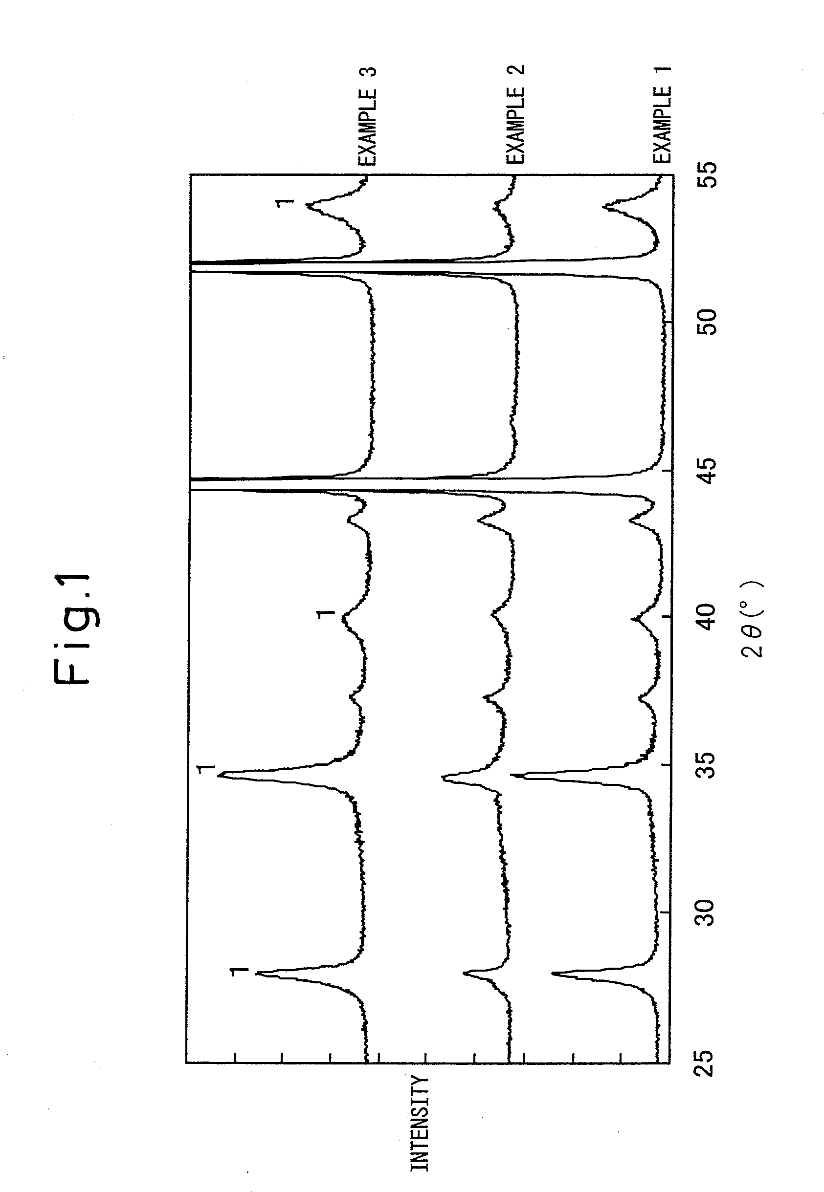
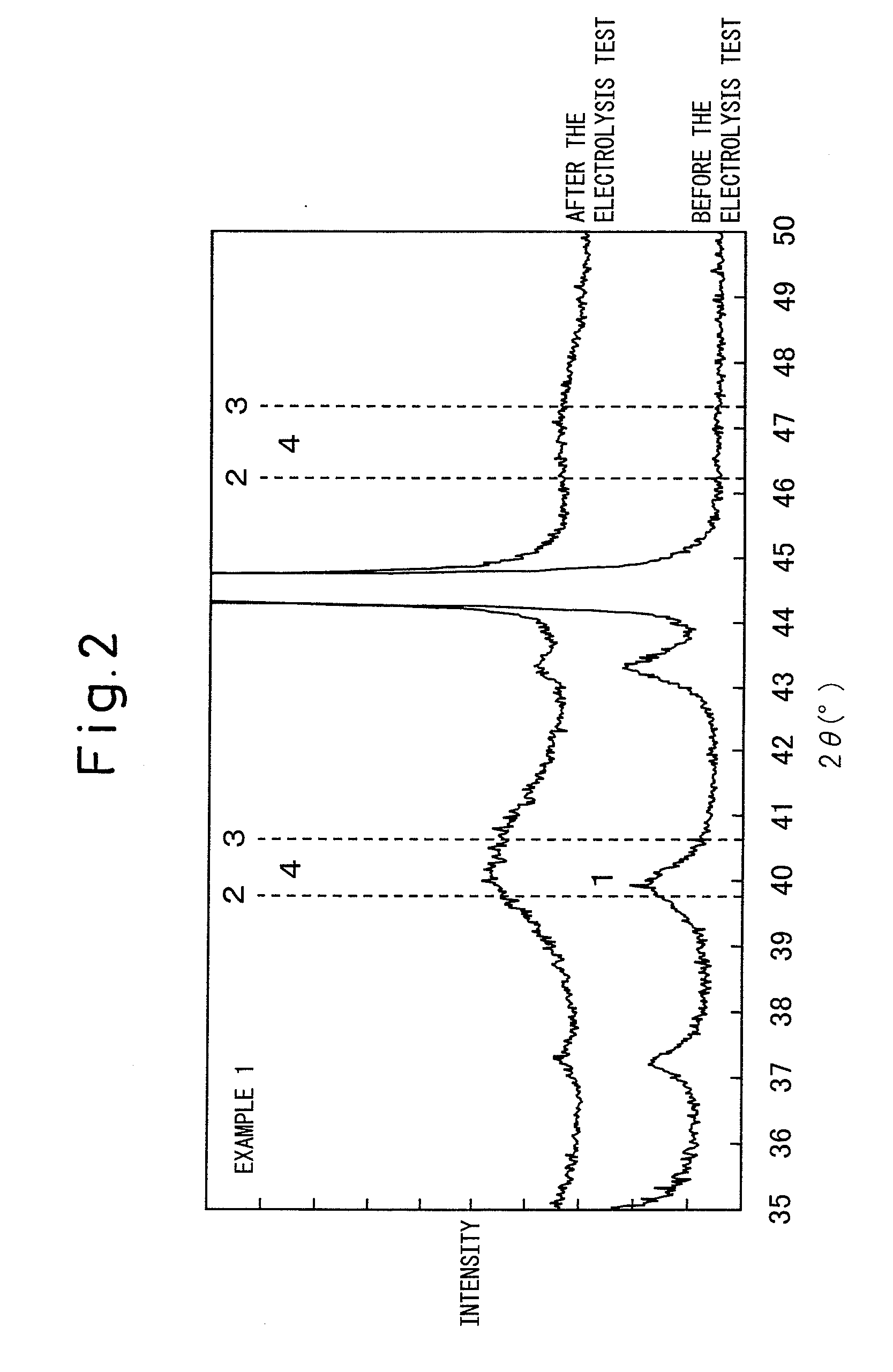
[0097]In the X-ray diffraction peaks before the electrolysis test (FIG. 1), the peak of iridium oxide can be clearly observed whereas a clear peak of metal platinum cannot be observed. From this, it can be understood that the catalyst layer before the electrolysis test is composed of crystalline iridium oxide and amorphous platinum. In addition, the full width at half maximum of the X-ray diffraction peak) (2θ=34.70° of iridium oxide was 0.42°. Similarly to in Example 1, it can be understood that iridium-platinum alloy had been formed from the X-ray diffraction peak...

example 3

[0099]A cathode was prepared and evaluated in the same way as in Example 1, except that the cathode was subjected to the thermal decomposition at 470° C. for 10 minutes, and further subjected to the post-heat treatment at 470° C. for 1 hour after the thermal decomposition.

[0100]In the X-ray diffraction peak (FIG. 1) before the electrolysis test, the clear peak of iridium oxide can be observed whereas a clear peak of metal platinum cannot be observed. From this, it can be understood that the catalyst layer before the electrolysis test is composed of crystalline iridium oxide and amorphous platinum. In addition, full width at half maximum of the X-ray diffraction peak (2θ=34.70° of iridium oxide was 0.46°. Furthermore, similarly to as in Example 1, it can be understood that iridium-platinum alloy had been formed from the X-ray diffraction peaks after the electrolysis test.

[0101]As shown in Table 1, as a result of the salt electrolysis test by the ion-exchange membrane process, the hyd...


PUM

PropertyMeasurementUnit
aaaaaaaaaa
temperatureaaaaaaaaaa

Abstract

The present invention provides an excellent durable cathode for hydrogen generation, which has a low hydrogen overvoltage and reduced dropping-off of a catalyst layer against the reverse current generated when an electrolyzer is stopped, and a method for producing the same. The present invention provides a cathode for hydrogen generation having a conductive base material and a catalyst layer formed on the conductive base material, wherein the catalyst layer includes crystalline iridium oxide, platinum and iridium-platinum alloy.

Description

TECHNICAL FIELD[0001]The present invention relates to a cathode for hydrogen generation used for electrolysis of water or an aqueous solution of an alkali metal compound, in particular, a cathode for hydrogen generation suitably used for electrolysis of salt by an ion-exchange membrane process.BACKGROUND ART[0002]A cathode for hydrogen generation has been used in electrolysis in which water or an aqueous solution of an alkali metal compound (typically an alkali metal chloride) is electrolyzed to produce hydrogen, chlorine, caustic soda, and the like. The major problem in electrolysis is reduction of energy consumption, more specifically, reduction in electrolytic voltage. In recent years, as an electrolytic process for an aqueous solution of an alkali metal chloride such as salt water, an ion-exchange membrane process is common, and various studies have been carried out now. When electrolysis is carried out, as an electrolytic voltage, in addition to a voltage theoretically required...

Claims


Application Information

Patent Timeline
Patent Type & Authority Applications(United States)
IPC IPC(8): C25B11/04C25B9/00C25D7/12B05D5/12
CPCC25B11/0494C25B11/0484C25B11/097C25B11/093
Inventor SASAKI, TAKEAKIFUNAKAWA, AKIYASUMATSUSHITA, TADASHIHACHIYA, TOSHINORI
Owner ASAHI KASEI KK
Why Eureka
Try Eureka