In 2009 around 20 commercial prototypes were under development, but no commercially successful wave
energy system is yet in operation.
The main problems are:Low efficiency of energy capture and conversionHigh life-cycle costsStorm damage riskEnvironmental
impactLow efficiency of conversion of available wave energy arises from:Poor location.
The combination of these effects randomizes
wave period and
wave height in many near-
shore locations, making efficient energy capture in such locations impossible.
Such devices are limited to capturing no more than 50% of available wave energy.Wave-bridging.
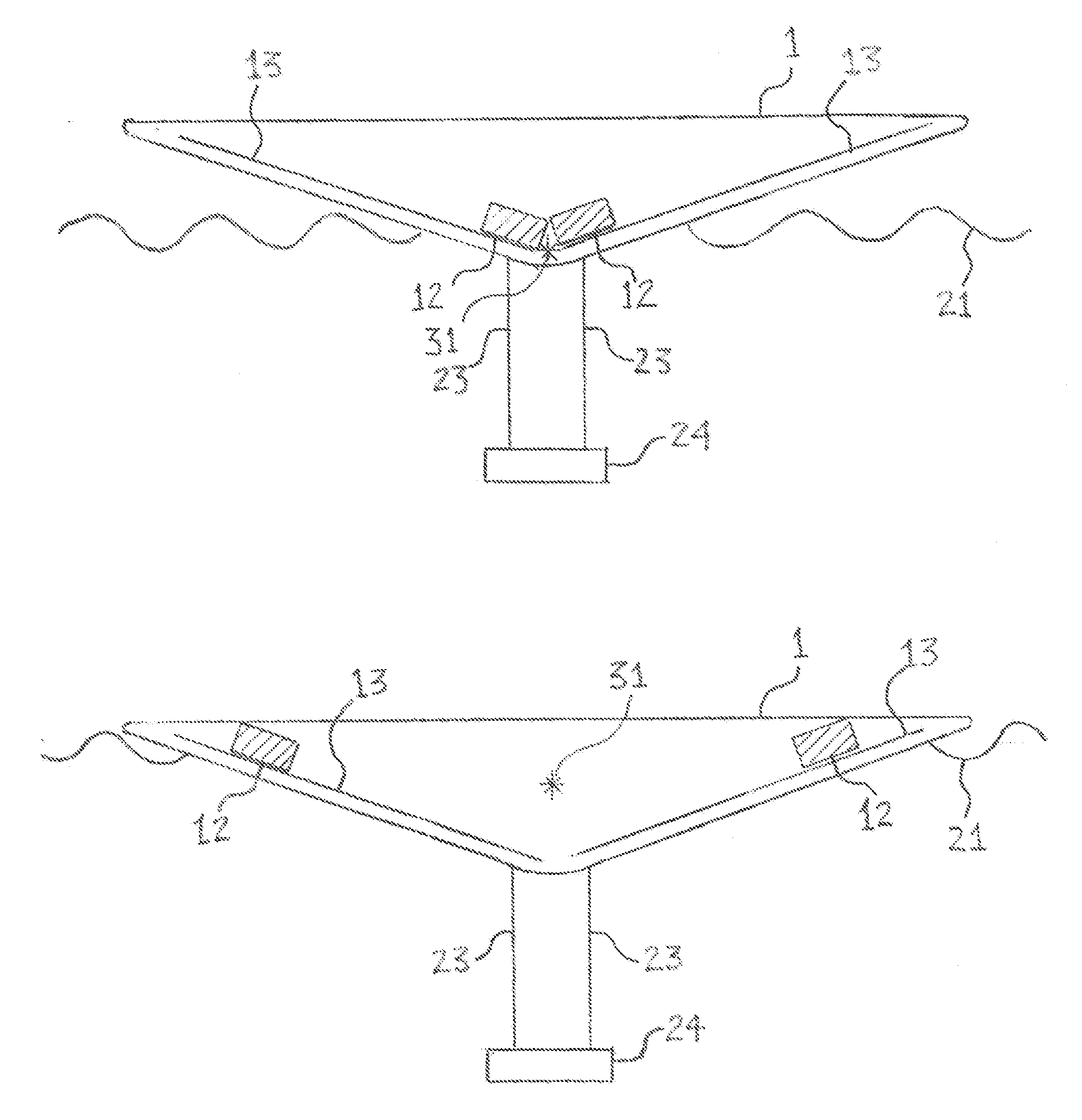
A pitching floating vessel captures potentially both surge and heave vectors of wave energy but is subject to wave-bridging.
If the vessel is shorter than this it tends towards less efficient bobbing.
A vessel that is optimized to
pitch at long wave-lengths is inefficient at short wave-lengths and vice versa.
An obvious but incomplete solution is to design the vessel to
pitch at the frequency that delivers most energy over the year.
Non-resonant interaction between wave energy devices and ocean
waves is highly inefficient.
However,
wave frequency varies widely over time so that this strategy is only partly effective.
Phase-forcing is only partly effective in raising efficiency because it works by stopping the transfer of energy.Restricted bandwidth.
A
rational design of WEC does not attempt to capture the entire wave
energy spectrum because the cost of capturing the infrequent top and bottom percentiles of wave energy is uneconomic.
Variation in only one of these terms does not suffice to enable a wide range of pitching periods.
For example, a long vessel with a large water-plane cannot in any practical way be made to
pitch rapidly only by moving weights on the vessel.
Radiation losses.
Such designs have reduced efficiency.
There can be similar losses from tether systems.Tuning losses.
Where dynamic tuning is implemented there will be losses due to slow or inefficient tuning and the energy absorbed in tuning, for example, in moving
ballast masses.Conversion losses.
As a result of the factors listed above, the efficiency of conversion of wave energy to electrical power for most described WECs is low: it is estimated that only a few devices achieve efficiencies above 15%.
High life-cycle costs arise from:High capital costs.
These will be high if expensive materials or unusual shapes or construction methods are required, if the device is complex or if major under-sea work is required, for example to build a fixed platform.
Excessive unconstrained side stresses on operating mechanisms may require costly over-design to avoid wear and damage.High operating costs.
In the marine environment these are likely to corrode, erode, distort, leak and jam, reducing performance and requiring frequent maintenance.
Maintenance costs and the costs of
downtime will be high if the device is prone to failure and especially if it must be towed to port for repair.
Location of such devices is limited by the availability of adequately large or well-equipped local ports.
Storm damage and rogue
waves are a major risk for wave energy devices.
Any fixed, non-submersible device is vulnerable and can be protected only by costly over-design.
This limits the commercial scope for near-
shore structures.
Avoidance of costly and obtrusive structures requires that the
pendulum is not a conventional simple pendulum since this requires a vessel around 70 m high to permit
resonance at 16 seconds.
However a combination of pitching vessel and pendulum is less common and there is little prior art that describes WECs with dynamic tuning of both pitching vessel and pendulum.
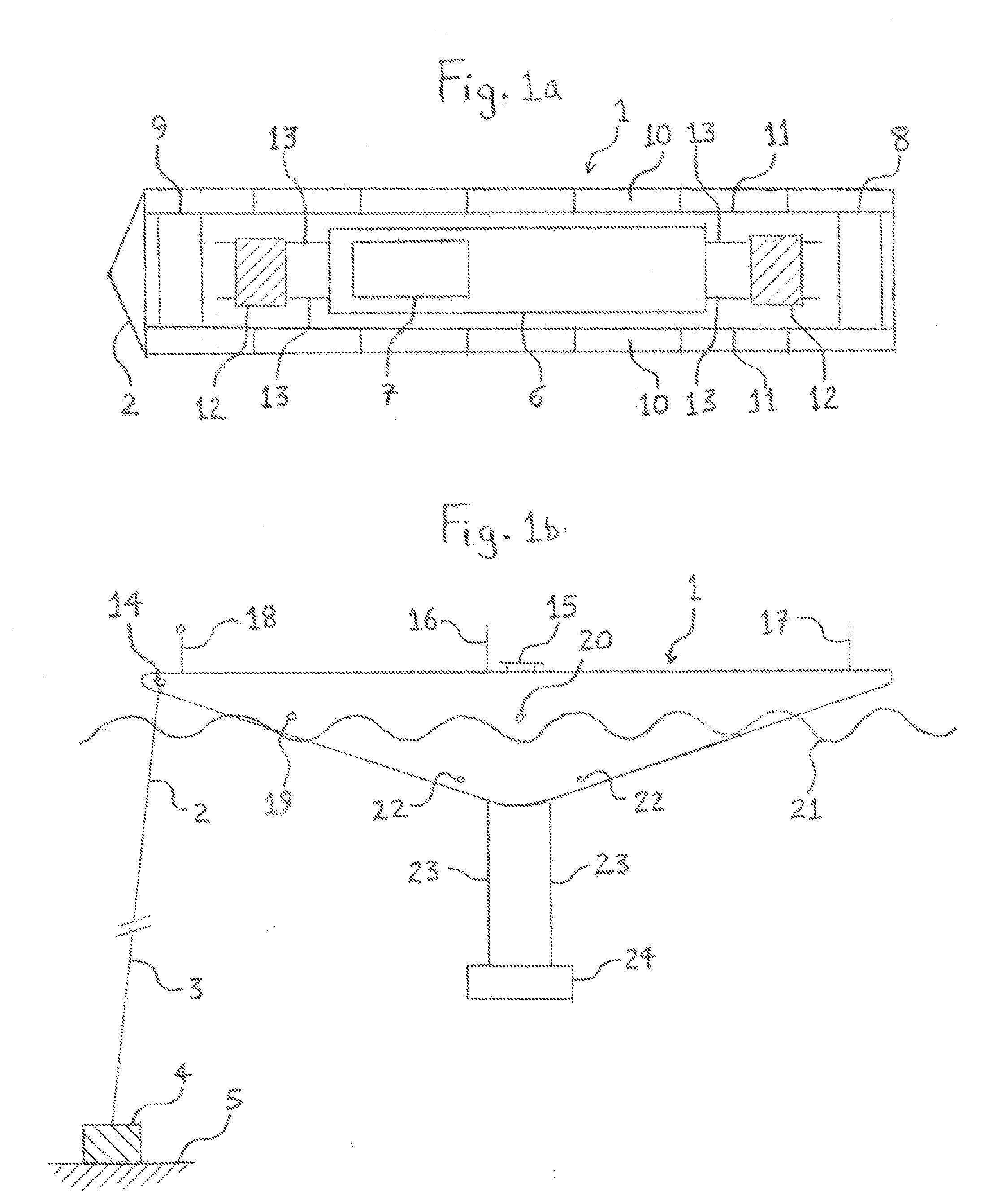
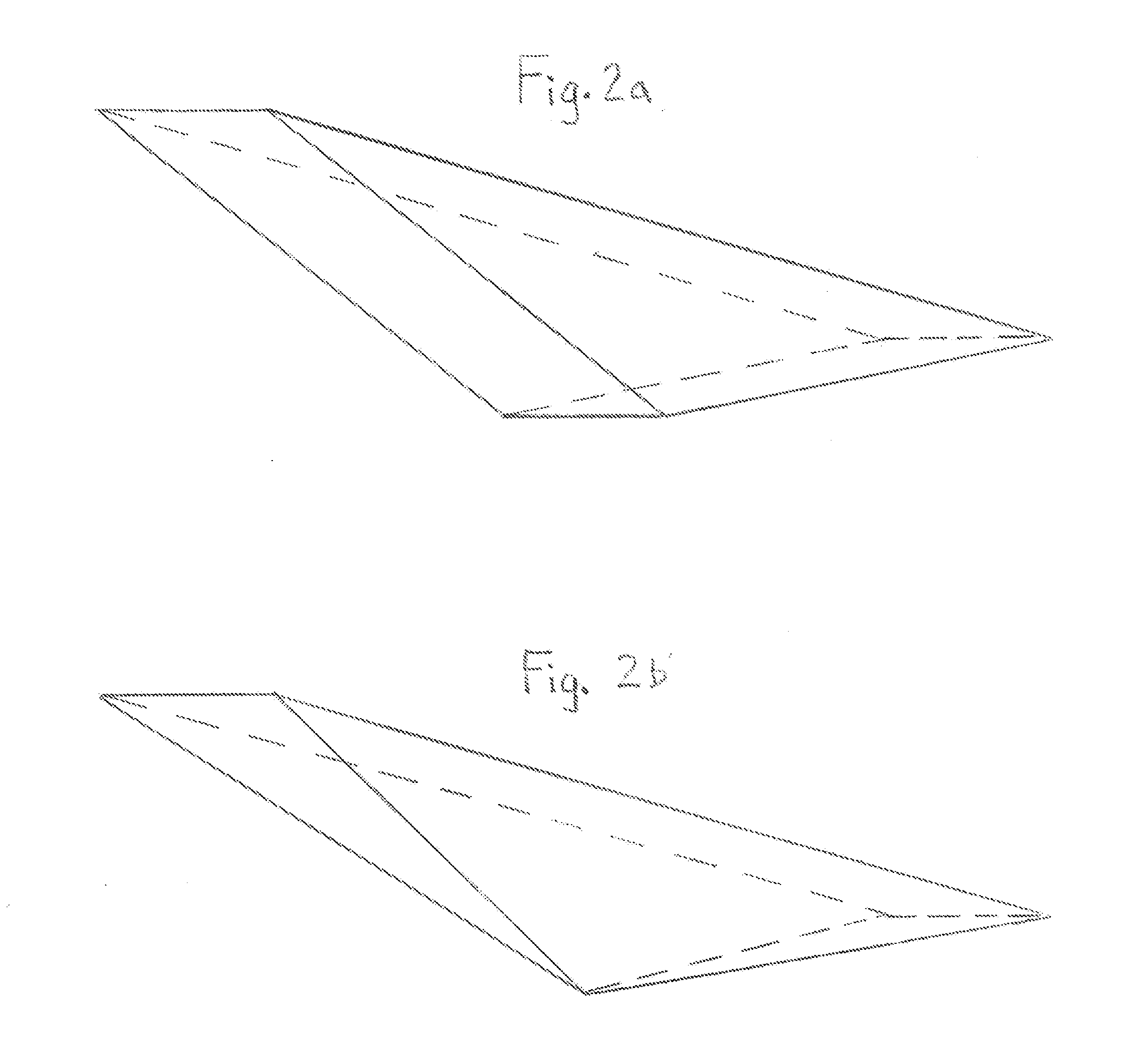
This
hull shape further enhances pitching response but at the price of greater
instability

