Ultrashort pulse laser applications

a technology of ultrashort pulse and laser, applied in the field of ultrashort pulse laser applications, can solve the problems of ineffective separation or removal of biological tissue layers, damage to underlying layers or surrounding tissue, and waste of instruments,

Inactive Publication Date: 2011-04-21
GUO ZHIXIONG +3
View PDF5 Cites 31 Cited by
  • Summary
  • Abstract
  • Description
  • Claims
  • Application Information

AI Technical Summary

Benefits of technology

[0014]In yet other embodiments, the invention relates to a method of precision separating a transverse layer from a biological tissue without damaging the surface of the transverse layer or the tissue surrounding the separated layer, comprising applying a USP laser to the tissue. In certain further embodiments, the method further comprises: (i) generating a laser beam of USP, wherein the pulses have a duration of about 100 fs to about 50 ps, a repetition rate of about 1 Hz to about 500 kHz, a pulse energy of about 1 to about 100 μJ, and a wavelength of between about 776 nm and 1552 nm; (ii) focusing the beam to the biological tissue at a first site, wherein the focused beam induces optical breakdown and ablates at a depth below the transverse layer at the first site; and (iii) repeating the application of the focused beam to the biological tissue at a plurality of sites across the biological tissue, wherein the focused beam induces optical breakdown and ablates below the entire transverse layer. In some embodiments, the USP laser is applied in a direction normal to the surface of the transverse laser. In other embodiments, the USP laser is applied in a direction parallel to the surface of the transverse layer. In certain further embodiments, the method fur...

Problems solved by technology

For instance, the tissue may have to be separated into layers, as the tissue in its entirety may not be necessary or appropriate for implantation.
However, the field lacks an effective method for separating or removing layers of biological tissue, or for cutting and shaping the tissue.
Techniques using a mechanical cutter or surgical knife to separate a tissue into layers or cut the tissue into portions are often imprecise and can result in damage to the underlying layers or surrounding tissue, respectively.
These instruments also tend to be wasteful, as tissue is lost due to the width of the blade or cutters.
Traditional continuous wave lasers can be use...

Method used


Image

  • Ultrashort pulse laser applications
  • Ultrashort pulse laser applications
  • Ultrashort pulse laser applications

Examples


example 1

Experimental Set-Up

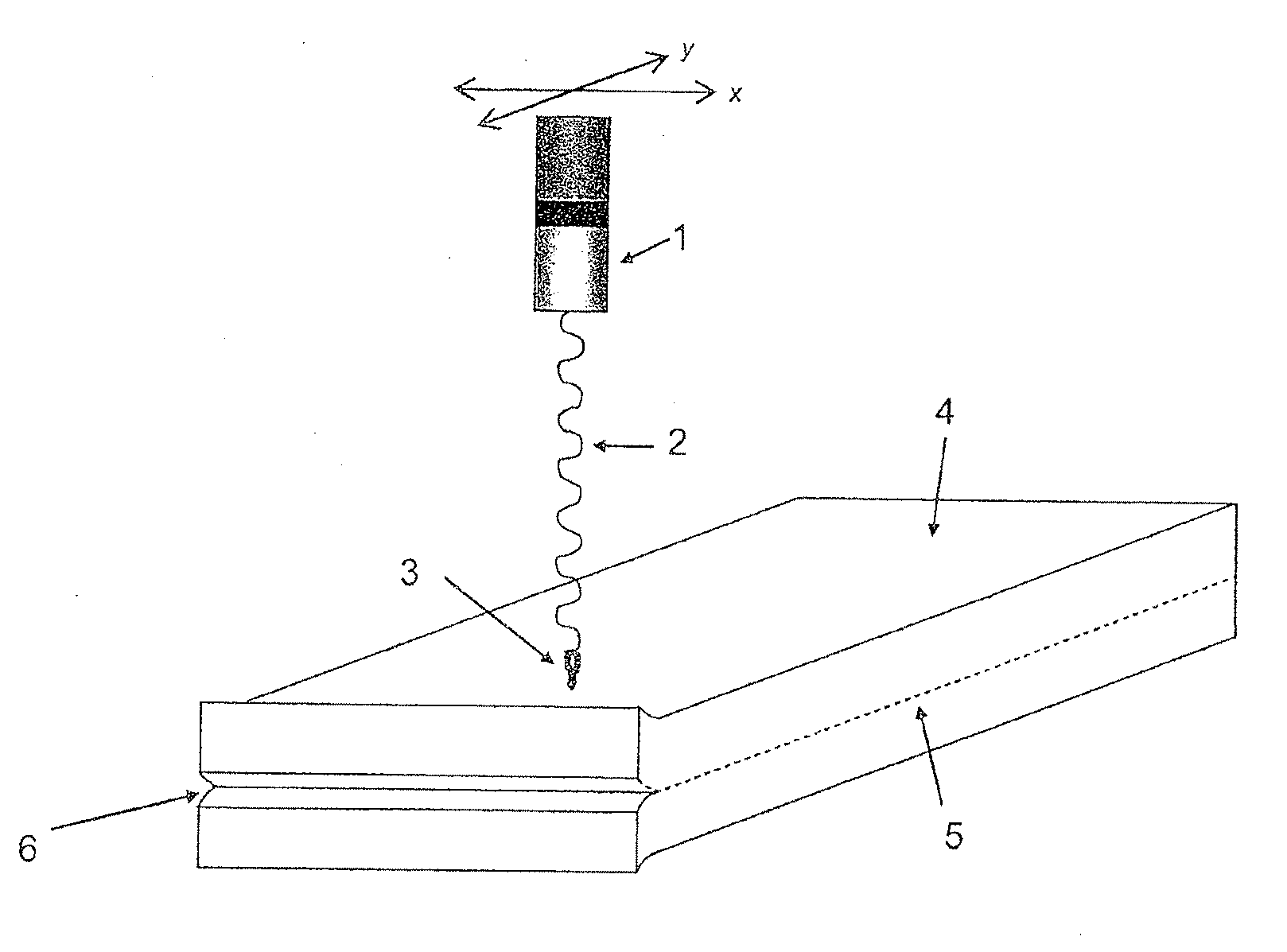
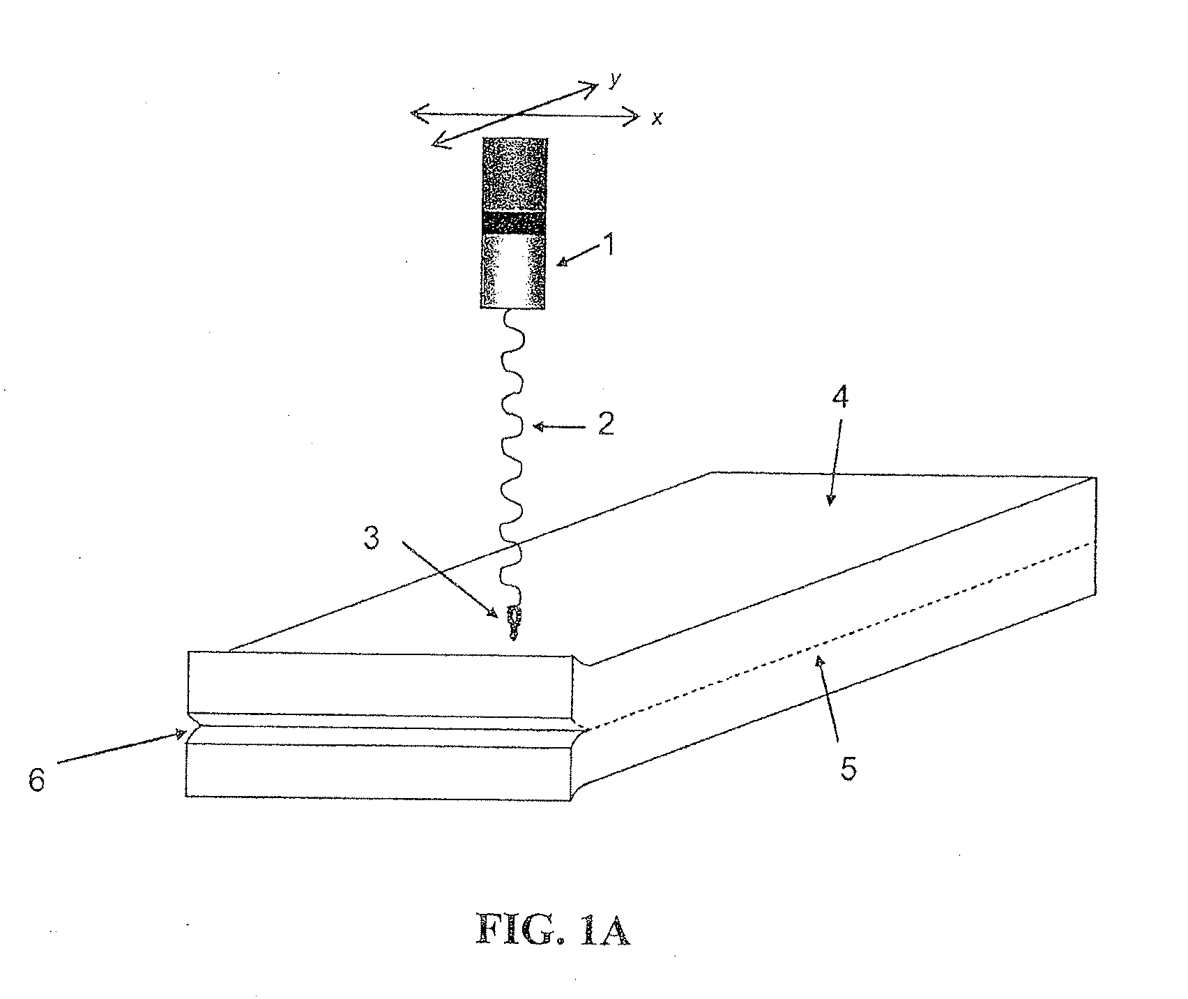
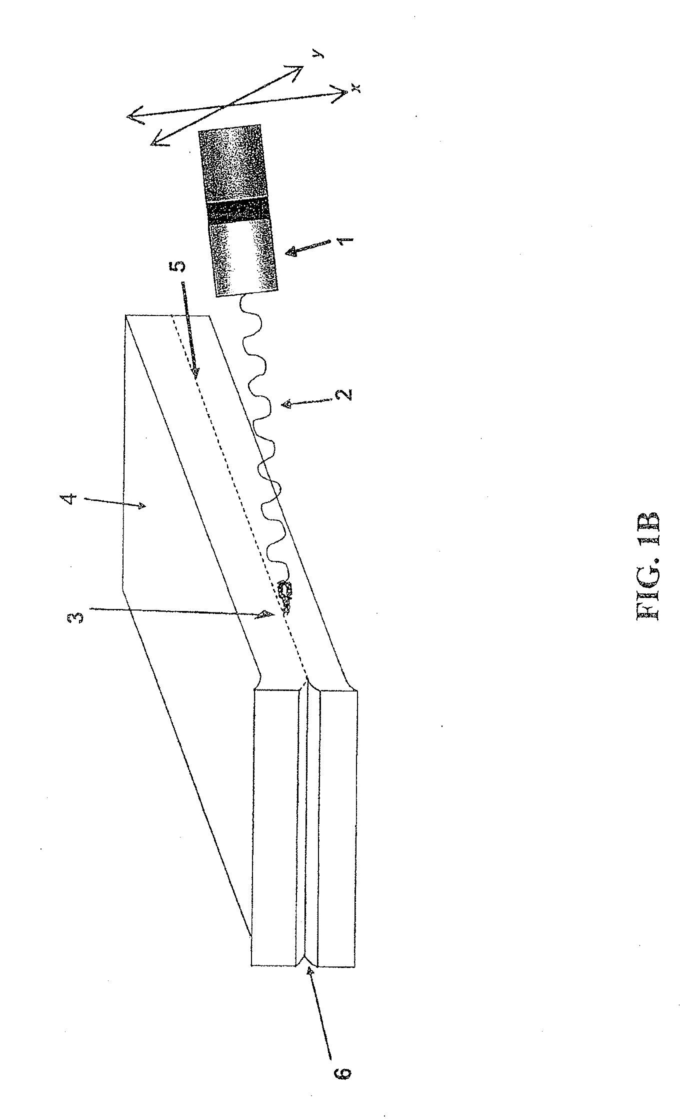
[0118]A schematic of the experimental setup is shown in FIGS. 2a and 2b. An Erbium Doped Fiber Laser (Raydiance, Inc) operates at wavelength 1552 nm with a pulse duration of 1.1 pico-second was used in the experiments. The repetition rate is tunable between 1 to 500 KHz and the pulse energy is variable between 1-5 μJ. The laser beam generated by the system was modified by an astigmatism correction mirror and was launched into a long working distance objective lens (M Plan Apo NIR 20x / 0.4 N.A., Mitutoyo). The energy loss after the lens is about 50-60%. The output focused beam has a diameter of about 8 μm.

[0119]The target sample was fixed to a lab-made attitude adjustable work fixture which was placed on a programmable 3-D automated Precision Compact Linear Stage (VP-25XA, Newport). The automated stage moves at a speed range between 1-25 mm / s.

[0120]In an alternative set-up, the stage can remain stationary while the laser source is mobile, or both the stage and the l...

example 2

Ablation of Growth Media by USP Laser

[0123]USP laser beam was applied to a collagen gel having mold growth on its surface to determine whether the beam can remove the mold from the collagen gel surface. The beam was applied at the parameters shown in Table 2.

TABLE 2Parameters of USP laser used for ablating mold on a collagen gel.Pulse ParameterSettingDuration1.1 psEnergy5μJRepetition Rate5.05 kHzScanning Velocity5mm / sWavelength1552 nm

[0124]Mold was grown on the surface of a collagen gel, as shown in FIG. 4a. A magnified view of the surface of the collagen gel clearly shows that the mold grew across the surface of the gel (FIG. 4b).

[0125]The USP laser was applied at various working distances, i.e., the distances between the laser source and the sample. The effects of the USP laser on mold ablation are exhibited in FIGS. 4c and 4d, which show bands where the surface was ablated. The bands were generated by laser applied at different working distances, and suggest that the working dist...

example 4

Ablation of Blood from Slide Covered with a Packaging Material by USP Laser

[0137]USP laser beam was applied to a slide having blood on its surface, such that the slide is covered with a translucent packaging material, in order to demonstrate the capability of the USP laser to ablate a surface through another material. The beam was applied at the parameters shown in Table 7.

TABLE 7Parameters of USP laser used for ablating blood from a slide.Pulse ParameterSettingDuration1.1psEnergy5μJRepetition Rate5.05kHzScanning Velocity5mm / sWavelength1552nm

[0138]A transmission test of the packaging materials (TYVEK and KAPAK) revealed how the beam was transmitted through the packaging. This is shown in Table 8.

TABLE 8Transmission test of package materials.Package ComponentTransmission at wavelength 1552 nmSecond layer89.6%First layer, plastic side89.8%First layer, fiber side15.9%

[0139]The USP laser beam ablated the blood from the surface of the slide through the packaging material. While the slide...


PUM


Abstract

The invention relates to methods of processing biological tissue using an ultrashort pulse (USP) laser. In one embodiment, the invention relates to a method of separating transverse layers or portions of a biological tissue using USP laser. In an alternative embodiment, the invention relates to a method of cutting biological tissue using USP laser. In another embodiment, the invention relates to a method of removing unwanted material from the surface of a biological tissue comprising application of the USP laser to the tissue surface.

Description

CROSS-REFERENCE TO RELATED APPLICATIONS[0001]This application claims the benefit of priority of U.S. Provisional Application Ser. No. 61 / 045,949, filed Apr. 17, 2008, which is hereby incorporated by reference in its entirety.BACKGROUND OF THE INVENTION[0002]Allograft, xenograft, or autograft tissues require processing before they can be transplanted into a patient or subject. These processing methods include preparing the tissues by cutting and shaping the tissues into a form appropriate for implantation, or removing unwanted materials from its surface.[0003]For example, allograft, xenograft, and autograft tissues often have to be modified into a particular form before implantation. This includes separating or removing layers of the tissue, or cutting the layer into a specific size or shape. For instance, the tissue may have to be separated into layers, as the tissue in its entirety may not be necessary or appropriate for implantation. In treatment of burn wounds, it may be necessar...

Claims


Application Information

Patent Timeline
IPC IPC(8): A61B18/20
CPCA61B18/20A61B2018/00452A61B2017/00761A61B18/203
Inventor GUO, ZHIXIONGSCHULER, MICHAELHUANG, HUANWANG, XIAOLIANG
Owner GUO ZHIXIONG
Why Eureka
Try Eureka