Amplifier linearizer

a linearizer and amplifier technology, applied in the field of electrical components, can solve the problems of limiting the performance of state-of-the-art electronic systems, affecting the linearity of amplifiers, so as to improve the linearity of power amplifiers, and improve the performance of power amplifiers. the effect of high performan

Active Publication Date: 2011-04-28
TM IP HLDG LLC
View PDF8 Cites 46 Cited by
  • Summary
  • Abstract
  • Description
  • Claims
  • Application Information

AI Technical Summary

Benefits of technology

[0009]The present invention overcomes these and other deficiencies of the prior art by providing an advanced adaptive predistortion linearization technique to dramatically reduce nonlinear distortion in power amplifiers over a very wide instantaneous bandwidth (up to 2 GHz) and over a wide range of amplifier types, input frequencies, signal types, amplitudes, temperature, and other environmental and signal conditions. The present invention adaptively tracks nonlinear distortion and cancels out the errors. Advanced processing is performed in the background in real-time to adaptively track parameters that drift. By compensating for nonlinear compression effects in power amplifiers, the technique improves the amplifier efficiency by operating closer to saturation than with traditional amplifiers. Therefore, lower power, lower mass, and lower cost amplifiers can be used in place of inefficient, high-power amplifiers.
[0013]The application of the linearity error compensation technique according to the present invention provides numerous advantages such as improving and maintaining extremely high performance of power amplifiers over a wider range of signal and environmental conditions, and adaptively tracking and correcting parameters which may drift with time, temperature, frequency, amplitude, etc. The present invention simplifies or eliminates outboard calibration, significantly improves power amplifier performance, provides built-in test capability (i.e., system failures can be detected and analyzed), and increases reliability of power amplifiers. The adaptive processing algorithms of the present invention efficiently share processing resources already present in adaptive systems (e.g., adaptive digital beamforming), and reduce the performance requirements of the analog circuitry because the digital signal processing is used to dramatically improve performance. In sum, the present invention lowers the cost, power, and size of power amplifiers while improving linearity and efficiency.

Problems solved by technology

This causes interference on other frequency channels.
Power amplifier linearity and efficiency are crucial issues in the design of electronic systems.
However, the more efficient power amplifier configuration is used the more nonlinear it usually becomes.
Linearity errors in power amplifiers cause harmonic distortion and intermodulation distortion, which can limit the performance of state-of-the-art electronic systems such as, but not limited to radar systems, digital transceivers for wireless 3G and 4G communications, laboratory test equipment, medical imaging, and audio and video compression.
All conventional linearization methods are limited in their maximum correctable range, which is the region of power output level near the onset of saturation.
One method, known as a feedforward technique, is frequently employed and improves linearity, but results in poor power amplifier efficiency.
However, for advanced RF systems with very high instantaneous bandwidths, transfer functions based on second-order or third-order polynomials are not accurate enough to prevent all non-linear distortion.
In fact, many RF devices produce irregular nonlinearities that are difficult to model with standard, integer-power polynomial functions.
However, when operating conditions vary, e.g., temperature, time, or frequency, the transfer function may no longer be suitable to adequately remove non-linear distortion.

Method used


Image

  • Amplifier linearizer
  • Amplifier linearizer
  • Amplifier linearizer

Examples


Embodiment Construction

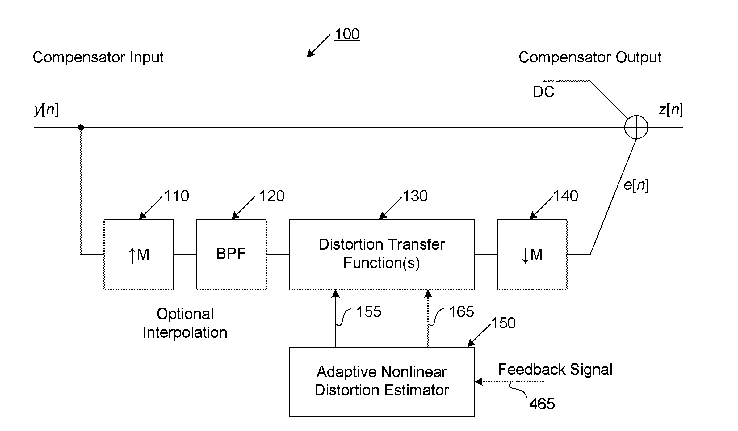
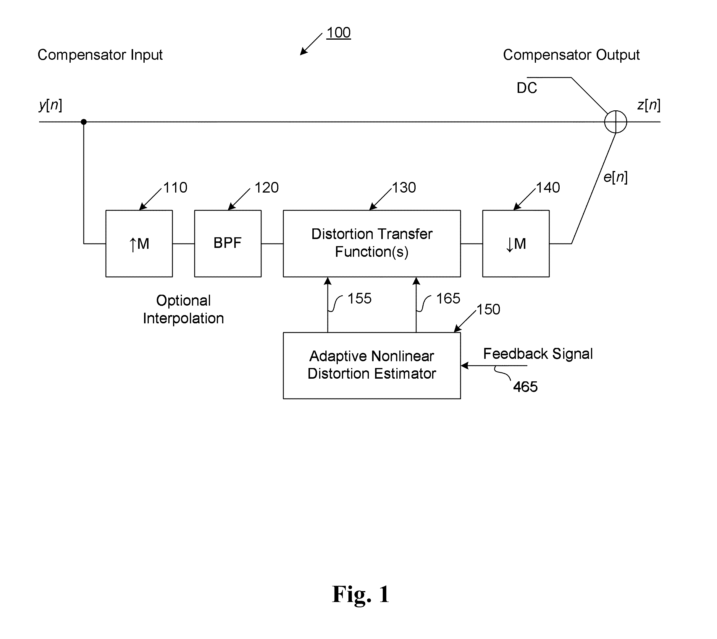
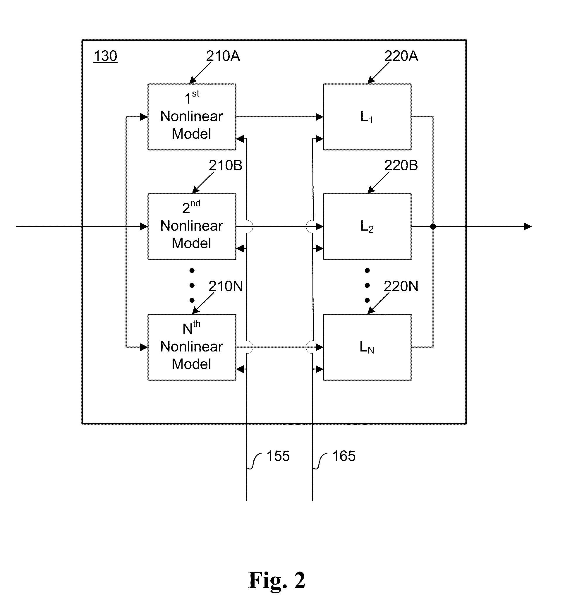
[0023]Further features and advantages of the invention, as well as the structure and operation of various embodiments of the invention, are described in detail below with reference to the accompanying FIGS. 1-7, wherein like reference numerals refer to like elements. Although the present invention is described in the context of power amplifiers, one of ordinary skill in the art readily appreciates that the linearization techniques described herein are applicable to any type of electronic component where it is desired to accurately and adequately eliminate inherent non-linear errors.

[0024]In general, the predistortion linearization circuitry of the present invention implements, among other things, (1) a higher-order polynomial model of an amplifier's gain and phase characteristics—higher than a third-order polynomial model; (2) an adaptive calibration technique; and (3) a heuristic calibration technique. The higher-order polynomial model is generated by introducing, for example, a pl...


PUM


Abstract

The present invention provides an advanced adaptive predistortion linearization technique to dramatically reduce nonlinear distortion in power amplifiers over a very wide instantaneous bandwidth (up to 2 GHz) and over a wide range of amplifier types, input frequencies, signal types, amplitudes, temperature, and other environmental and signal conditions. In an embodiment of the invention, the predistortion linearization circuitry comprises (1) a higher-order polynomial model of an amplifier's gain and phase characteristics—higher than a third-order polynomial model; (2) an adaptive calibration technique; and (3) a heuristic calibration technique. The higher-order polynomial model is generated by introducing, for example, a plurality of multi-tone test signals with varying center frequency and spacing into the power amplifier. From the power amplifier's corresponding output, the nonlinearities are modeled by employing a higher-order curve fit to capture the irregularities in the nonlinear transfer function. Different distortion transfer functions can be implemented for different operating conditions. The adaptive calibration technique is based on a feedback analysis technique, which updates the applicable distortion transfer function by analyzing the error signal between the introduced input signal and the output signal in real-time. The heuristic calibration technique implements different distortion transfer functions based on historical operating conditions and optimal configurations of the power amplifier.

Description

CROSS-REFERENCE TO RELATED APPLICATION[0001]The present application claims priority under 35 U.S.C. §119(e) to U.S. Provisional Patent Application No. 61 / 187,546, entitled “Amplifier Linearizer,” and filed Jun. 16, 2010, the disclosure of which is incorporated by reference herein in its entirety. The present application is also a continuation-in-part of and claims priority under 35 U.S.C. §120 to U.S. patent application Ser. No. 12 / 112,380, entitled “Adaptive Mismatch Compensators and Methods for Mismatch Compensation,” the disclosure of which is incorporated by reference herein in its entirety.BACKGROUND OF THE INVENTION[0002]1. Field of Invention[0003]The present invention relates to electronics and more specifically, to a technique for improving the linear performance of electrical components such as power amplifiers in radio frequency (RF) transceiver systems.[0004]2. Description of Related Art[0005]An electronic or power amplifier is a device for increasing the power of an inpu...

Claims


Application Information

Patent Timeline
Patent Type & Authority Applications(United States)
IPC IPC(8): H03F1/26H03F1/30
CPCH03F1/3247H03F3/19H03F1/3258
Inventor VELAZQUEZ, SCOTT R.
Owner TM IP HLDG LLC
Why Eureka
Try Eureka