Gas supply device, processing apparatus, processing method, and storage medium

a technology of gas supply device and processing apparatus, which is applied in mechanical equipment, instruments, transportation and packaging, etc., can solve the problems of low gas conductance of the internal gas flow channel of the showerhead, poor gas replaceability, and failure to deposit films on the wafer, etc., and achieves increased gas conductance of the gas flow channel to the substrate, easy manufacturing, and great flexibility in selection

Inactive Publication Date: 2011-04-28
TOKYO ELECTRON LTD
View PDF18 Cites 218 Cited by
  • Summary
  • Abstract
  • Description
  • Claims
  • Application Information

AI Technical Summary

Benefits of technology

[0033]According to the present invention, conductance of the gases in the flow channels to the substrate is increased and the gases are rapidly replaced in the gas-conducting space. In addition, the gas supply device of the invention is easy to manufacture, since the device, unlike the one used in related conventional technology, requires no precise, complex working of the members of various stages. This, in turn, yields a further advantage of great flexibility in selection of the kinds of useable materials. Moreover, applying the gas supply device to ALD or other schemes in which a film is deposited by supplying plural kinds of process gases cyclically in order leads to more rapid replacement of the gases within the gas supply device by means of a purging gas, thus contributing to the improvement of throughput.

Problems solved by technology

Because of their complexity and narrowness, internal gas flow channels of the showerhead have low gas conductance and are poor in gas replaceability.
This may contaminate the wafer W with particles or cause reaction products to directly stick as particles to the wafer surface, resulting in films failing to deposit on the wafer.
For these reasons, the purging time cannot be made too short and throughput is difficult to improve.
However, the gas showerhead has a complex, stacked structure, as described above, and fine-structured flow channels need to be formed.
While the shower plate 11, in particular, requires perforation with a large number of orifices, it is difficult to provide the above materials with such a fine-structuring process.
These situations have presented the problems that the showerhead 11 is difficult to manufacture and that the types of materials useable for the manufacture are limited.
However, JP-A-7-22323 does not describe solutions to the above-discussed problems occurring when the gases are replaced with each other.

Method used


Image

  • Gas supply device, processing apparatus, processing method, and storage medium
  • Gas supply device, processing apparatus, processing method, and storage medium
  • Gas supply device, processing apparatus, processing method, and storage medium

Examples


first embodiment

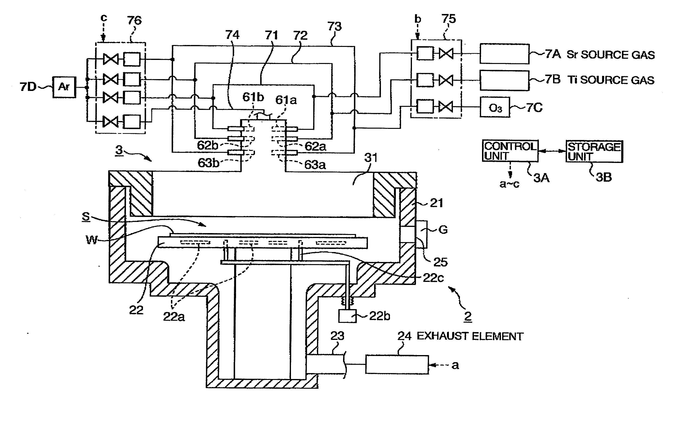
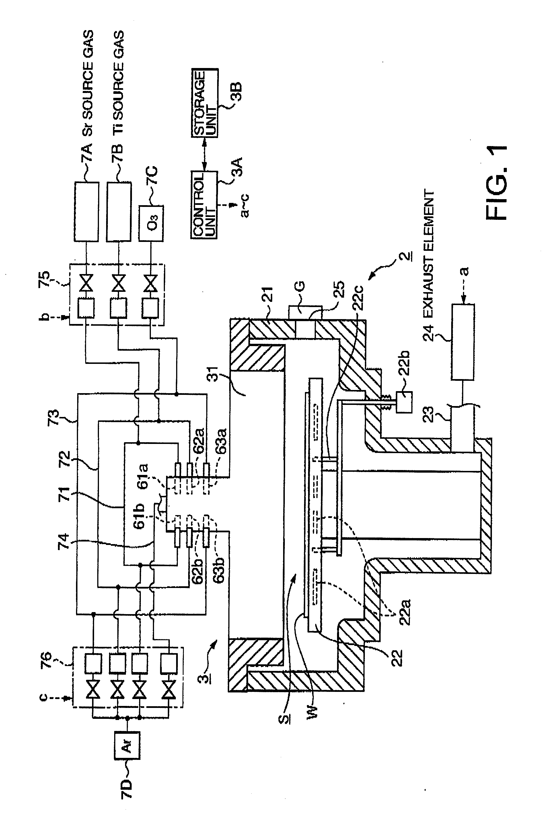
[0051]A total apparatus configuration of a film deposition apparatus 2, a first embodiment of the present invention, will be first described referring to FIG. 1.

[0052]The film deposition apparatus 2 according to the present embodiment has a function that uses an ALD process to deposit a thin film of strontium titanate (SrTiO3, hereinafter abbreviated to STO) as a highly dielectric material, on the surface of a semiconductor wafer (hereinafter referred to the wafer) W as a substrate. The deposition is accomplished by reacting a strontium-containing source gas (hereinafter referred to as the Sr source gas) as a first process gas, and a titanium-containing source gas (hereinafter referred to as the Ti source gas) as a second process gas, upon an ozone (O3) gas that is an oxidation gas as a third process gas.

[0053]The deposition apparatus 2 includes a process chamber 21. A mounting table 22 for mounting the wafer W horizontally thereon is provided in the process chamber 21. The mounting...

second embodiment

[0090]A second embodiment of the gas supply device constituting the gas supply unit of the above-described film deposition apparatus 2 is described below referring to FIG. 11(a).

[0091]Although constructed similarly to the gas supply unit 3, the gas supply unit 100 shown in FIG. 11(a) has none of the above-described partitioning members 41 to 46 in the gas-conducting space 32. Instead, the gas supply unit 100 has plate-like partitioning members 103 to 106 so as to partition the gas-conducting space 32 in a circumferential direction thereof. The partitioning members 103 to 106 each extend radially from a central portion of the gas-conducting space 32, towards an inner circumferential surface 33 of the device body 31.

[0092]For example, each partitioning member 103 to 106 is supported at one end thereof by the inner circumferential surface 33, and at the other end by a support 107 provided centrally in the radial direction. FIG. 11(c) is a perspective view of the partitioning members 10...

third embodiment

[0097]A third embodiment of the gas supply device constituting the gas supply unit of the above-described film deposition apparatus 2 is described below referring to FIG. 12, a sectional perspective view of the present embodiment. The description focuses primarily upon differences from the gas supply unit 3.

[0098]The gas supply unit 110 shown in FIG. 12 has its body 120 constructed into a flat, circular shape. In addition, a disc-shaped gas-conducting space 121 instead of the gas-conducting space 32 with a diametrally enlarged lower end is formed in the body 120. The gas-conducting space 121 includes no partitioning members 41 to 46, and has a plate-shaped member 111 at the diametrally enlarged lower end 121a of the gas-conducting space 121.

[0099]Slits 112 each circumferentially divided into four segments are concentrically opened in the plate-shaped member 111. FIG. 13(a) is a bottom view of the plate-shaped member 111, and FIG. 13(b) is a perspective view of the plate-shaped membe...


PUM

PropertyMeasurementUnit
height h2aaaaaaaaaa
height h2aaaaaaaaaa
timeaaaaaaaaaa

Abstract

A gas supply device 3 includes a device body 31 forming a substantially conical gas-conducting space 32 for conducting gases therethrough from a diametrally reduced end 32a of the space 32 to a diametrally enlarged end 32b thereof, gas introduction ports 61a to 63a, 61b to 63b, and 64, each provided near the diametrally reduced end 32a of the gas-conducting space 32 in the device body 31 to introduce the gases into the gas-conducting space 32, and a plurality of partitioning members 41 to 46 provided in the gas-conducting space 32 of the device body 31 to partition the gas-conducting space 32 concentrically. The partitioning members 42 to 46 arranged adjacently to each other at a radially outer side of the gas-conducting space 32 are greater than the adjacently arranged partitioning members 41 to 45 at a radially inner side in dimensionally diverging rate per partitioning member. Thus, internal gas flow channels of the gas supply device have high gas conductance and enhanced gas replaceability, compared with those of the conventional gas showerhead.

Description

FIELD OF THE INVENTION[0001]The present invention relates to a gas supply device for supplying process gases to a substrate, a processing apparatus including the gas supply device, a processing method using the gas supply device, and a storage medium.BACKGROUND OF THE INVENTION[0002]A gas showerhead is used as a device for supplying gases to an apparatus that conducts chemical vapor deposition (CVD), etching, and the like. The gas showerhead has a flattened columnar shape. The showerhead, when supplied with gases through gas introduction ports provided at its upper section, will supply the gases in shower form from a large number of orifices in a lower surface of the showerhead by diffusing the gases from an internal diffusion space. Two major known types of gas showerheads are available to supply multiple kinds of process gases. One type is so-called “premixing”, which mixes multiple kinds of process gases midway in one gas flow channel line before supplying the gases, and the othe...

Claims


Application Information

Patent Timeline
Patent Type & Authority Applications(United States)
IPC IPC(8): C23C16/455C23C16/458C23F1/08C23F1/00F17D1/04G06F17/00
CPCC23C16/409C23C16/45531C23C16/45565H01L21/0228C23C16/45591H01L21/02197C23C16/45582Y10T137/4673
Inventor TSUDA, EINOSUKE
Owner TOKYO ELECTRON LTD
Why Eureka
Try Eureka