Optical mode transformer, in particular for coupling an optical fiber and a high-index contrast waveguide
a transformer and optical fiber technology, applied in the field of optical mode transformers, can solve the problems of high coupling loss and high power loss of coupling, and achieve the effects of high index, efficient coupling of optical fibers, and efficient coupling of hc waveguides
- Summary
- Abstract
- Description
- Claims
- Application Information
AI Technical Summary
Benefits of technology
Problems solved by technology
Method used
Image
Examples
example 1
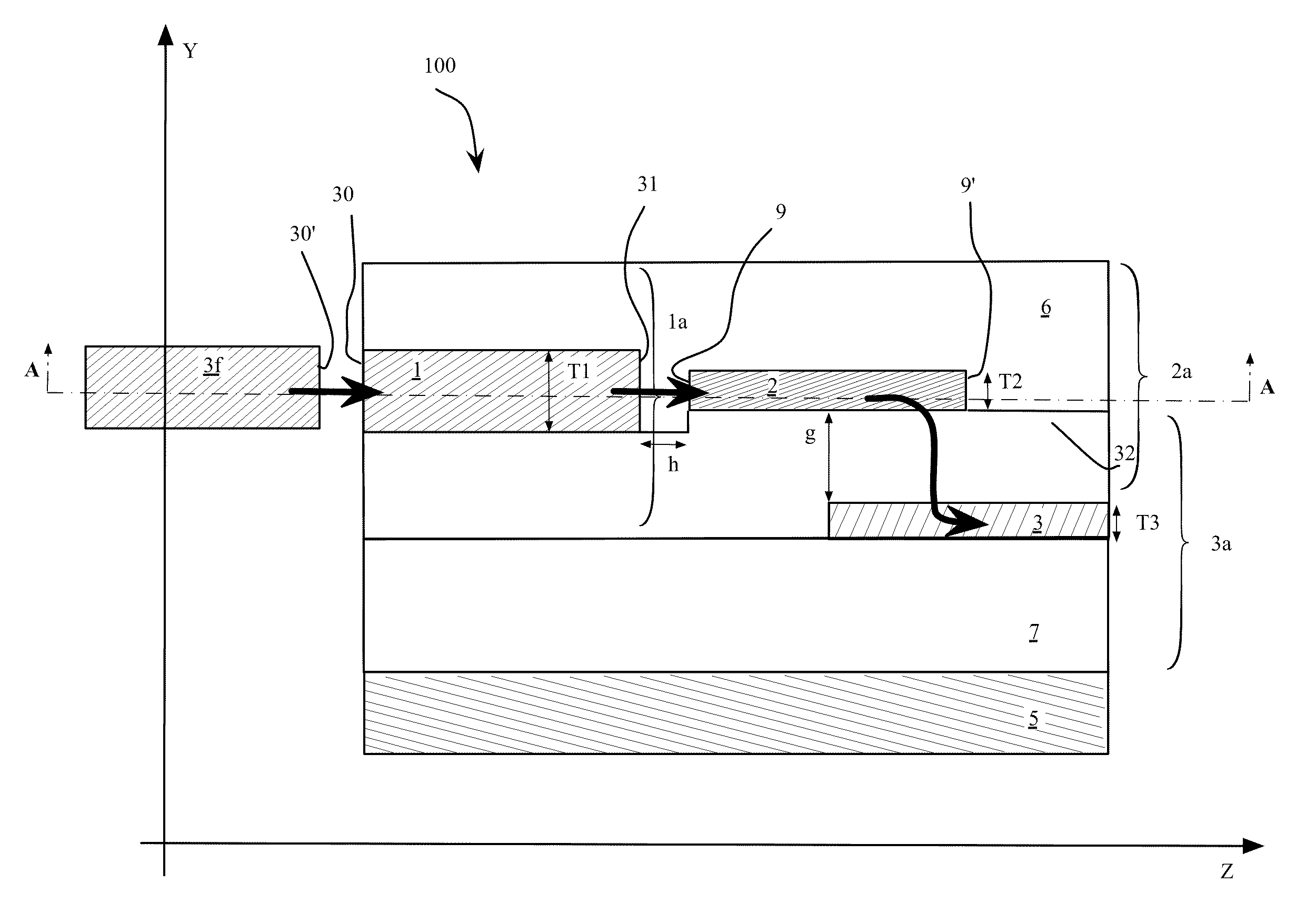
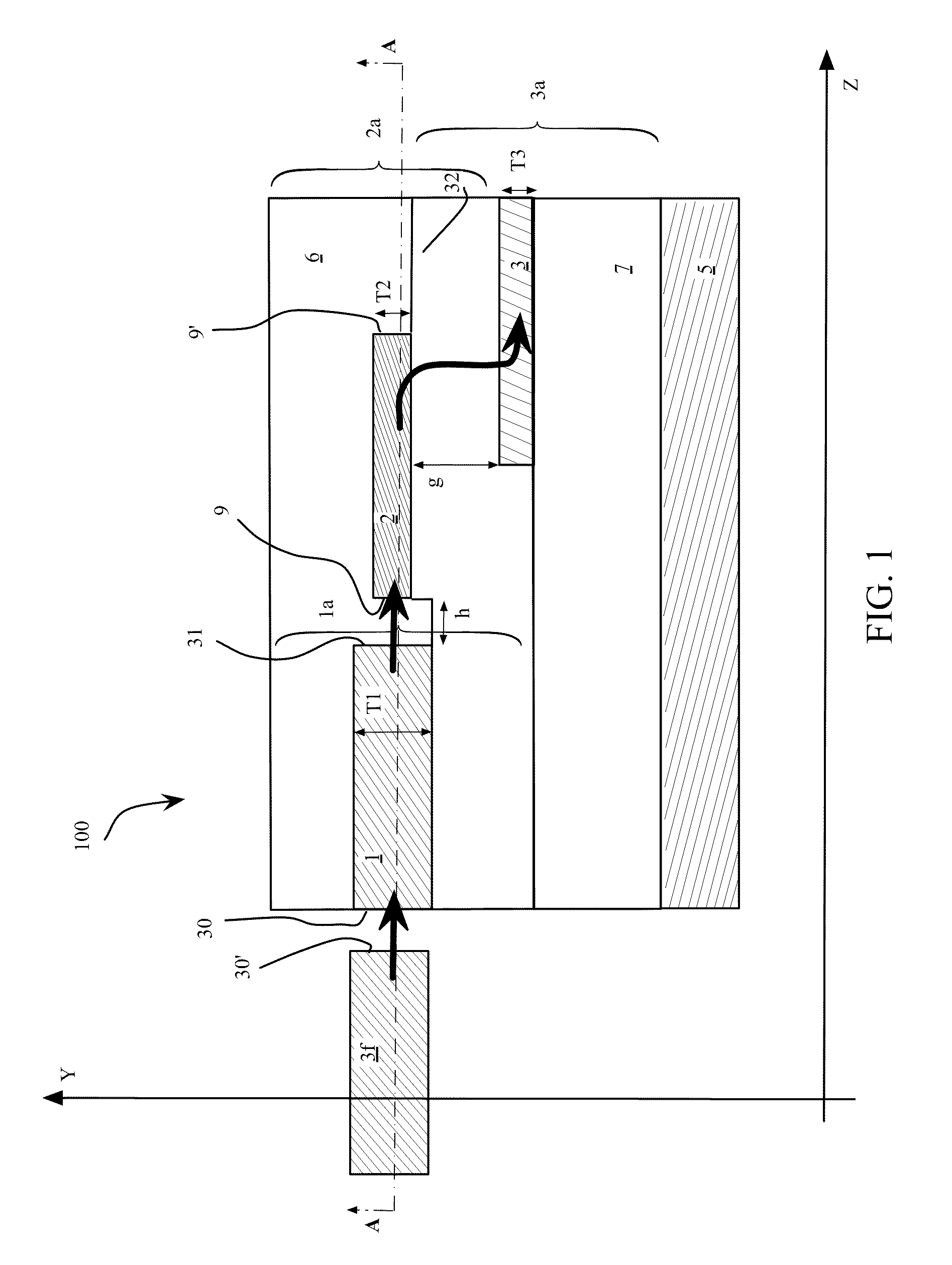
[0141]A germanium-doped SiO2 (SiO2:Ge) second waveguide core, with nsecond core=1.483 and Δn2=2.5% is vertically stacked on top of a 150 nm thick Si waveguide (nthird core=3.4756, Δn3=40%), the two being separated by a 1.2 μm oxide layer (TEOS) having ncladding=1.446 at 1550 nm. Second and third core are vertically aligned, i.e., no lateral misalignments exist between the second and the third waveguide. The thicknesses of both cores 2,3 remain substantially unchanged along the transformer 100 according to the present example (i.e., T2=2.6 μm and T3=150 nm).
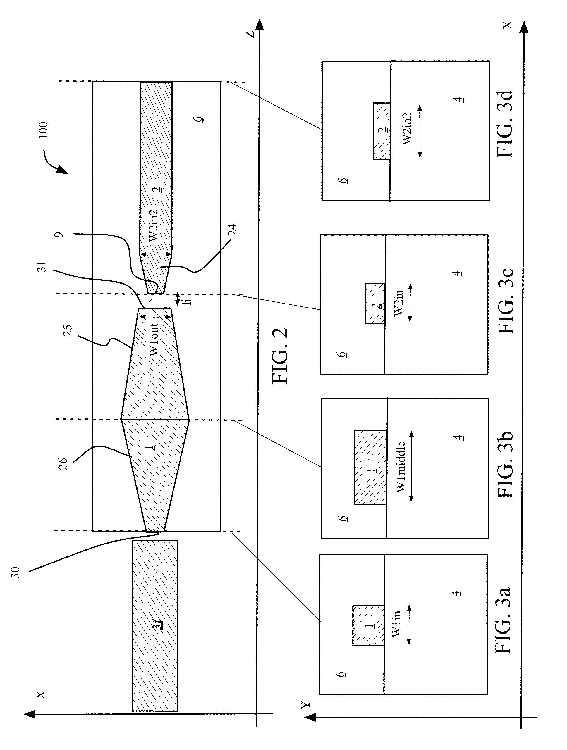
[0142]In this Example, the dimensions of the cores at the first cross section of FIG. 5a are W3IN=100 nm corresponding to the width of the taper tip realized in the Si waveguide, and W2IN2=T2=2.6 μm. The first section of the overlapping region has a length L1 equal to 500 μm. At the second cross section of FIG. 5b, the third core 3 has an intermediate width W3MIDDLE=200 nm, and the second core 2 is at its smallest width W2MIDDLE=1...
example 2
[0151]The transformer of the second example is a transformer identical to the transformer of Example 1, with the exception of the second core dimensions.
[0152]In detail, referring back to FIGS. 5a and 5b, the dimensions of the cores of the transformer in this Example 2 are the following. The guiding portion of the second waveguide core 2 has a constant cross section of 3.6 μm×1.5 μm, leading therefore to an input width at the cross section represented in FIG. 5a of W2IN2=3.6 μm for the second waveguide, while the width of the third waveguide core is, as in Example 1, W3IN=100 nm. The gap between the two cores is still of 1.2 μm. At the end of the first section, having L1 equal to 500 μm, i.e., at the position depicted in the second cross section of FIG. 5b, the third core 3 has an intermediate width W3MIDDLE=200 nm, and the second core 2 is at its smallest width W2MIDDLE=1.2 μm, which remains constant till the end of the overlapping region. At the output, i.e., at the end of the sec...
example 3
[0155]The same structure of Example 1 has been realized (same materials and waveguide dimensions), however second and third waveguides have 1 μm lateral misalignment. This embodiment is shown in the cross section FIG. 10, where the geometrical axes of the second and third waveguide core are schematically identified with a dot. The transformer is globally indicated with 100′. A 1 μm lateral misalignment stands for a distance along the X direction between the two waveguides core axes of d=1 μm. Numerical computer simulations have shown that polarization mixing takes place only to a minor extent in the transformer 100′ realized according to Example 3. The observed polarization coupling is limited to the amount of 20% and it is reversible, i.e., after a given propagating distance within the waveguide, the polarization state of the travelling mode “returns” to its input polarization at the entrance of the transformer. At the output of the tapered region of the third waveguide core, the o...
PUM
 Abstract
Description
Claims
Application Information
 - R&D
- Intellectual Property
- Life Sciences
- Materials
- Tech Scout
- Unparalleled Data Quality
- Higher Quality Content
- 60% Fewer Hallucinations
Browse by: Latest US Patents, China's latest patents, Technical Efficacy Thesaurus, Application Domain, Technology Topic, Popular Technical Reports.
© 2025 PatSnap. All rights reserved.Legal|Privacy policy|Modern Slavery Act Transparency Statement|Sitemap|About US| Contact US: help@patsnap.com


