Railroad signaling and communication system using a fail-safe voltage sensor to verify trackside conditions in safety-critical railroad applications

a voltage sensor and signaling system technology, applied in the field of fail-safe verification systems, can solve the problems of significant testing, high cost of prior art central control units, and high cost of safety-validated software, and achieve the effects of low power consumption, low cost, and low cos

Active Publication Date: 2011-05-19
WESTINGHOUSE AIR BRAKE TECH CORP
View PDF11 Cites 22 Cited by
  • Summary
  • Abstract
  • Description
  • Claims
  • Application Information

AI Technical Summary

Benefits of technology

[0022]The verification system and method of the present invention allows cost effective, single-chip microprocessors to be deployed as single input (single bit) fail-safe voltage sensors, replacing more expensive, multi-input prior art sensing equipment. Each sensor of the present invention is located near the electrical component it is sensing, thus obviating the need for wiring between each sensing point and a central communications controller as in the prior art equipment. The single-chip, single input arrangement of microprocessors as a fail-safe voltage sensor provides: protection against false reporting of a trackside circuit status (energized vs. non-energized), fast cycle time from application of power to the sensor to the reporting of energized status, flexible arrangement of multiple sensors into clusters for combining status messages reporting; and low power consumption and control over external communications devices to manage sleep-mode mechanisms for longer battery life at trackside installations which is particularly important at solar powered installations, and in embodiments utilizing wireless communications means, galvanic isolation of the input to be monitored from other circuits and power sources.

Problems solved by technology

These prior art central control units are expensive due, in large part, to the additional components and software needed to ensure the accuracy of the electric readings.
One disadvantage of the prior art system is that it requires expensive, safety-validated software for the microprocessor and significant testing to ensure that all failure modes have been addressed.
Maintaining such a software development process for the lifetime of the product burdens it with significant cost.
A second disadvantage of the existing system is that the microprocessor is centrally mounted in a trackside bungalow, and a significant amount of wiring is needed to reach the various sensing points.
This adds cost to the deployment into existing bungalows.

Method used


Image

  • Railroad signaling and communication system using a fail-safe voltage sensor to verify trackside conditions in safety-critical railroad applications
  • Railroad signaling and communication system using a fail-safe voltage sensor to verify trackside conditions in safety-critical railroad applications
  • Railroad signaling and communication system using a fail-safe voltage sensor to verify trackside conditions in safety-critical railroad applications

Examples


Embodiment Construction

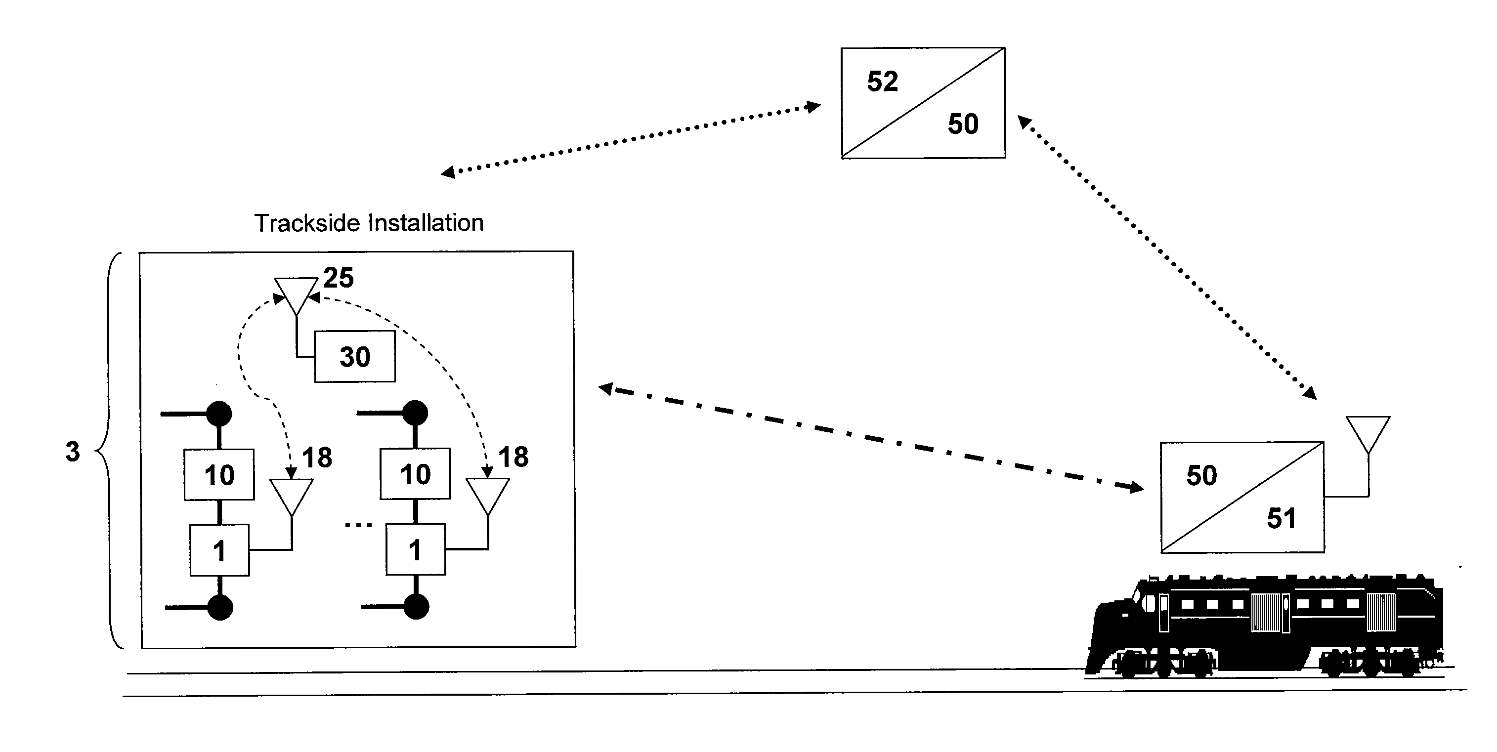
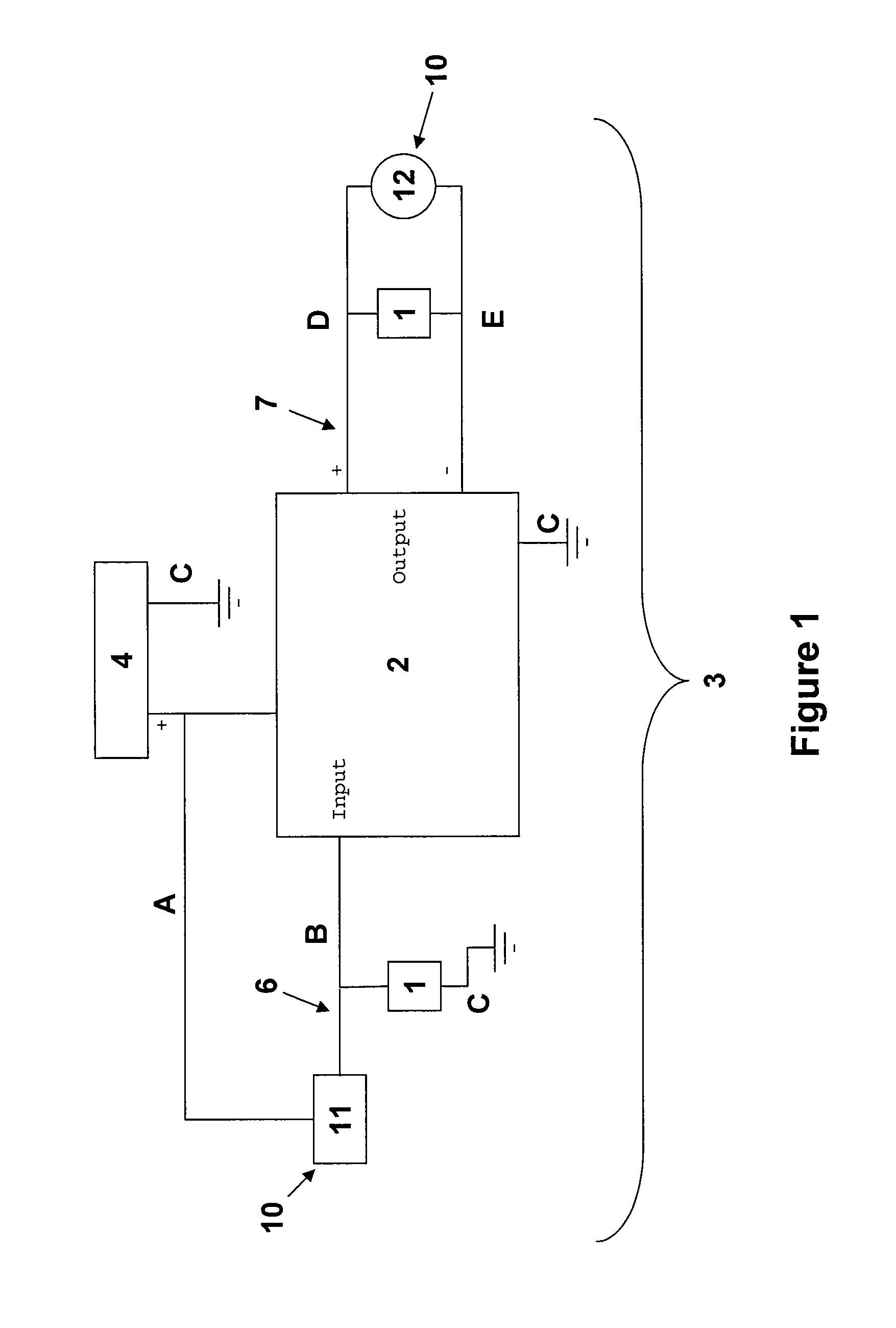
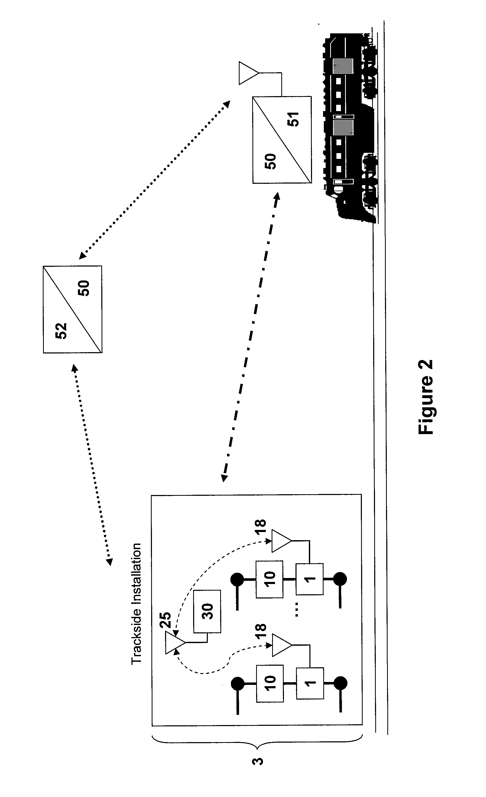
[0028]Referring now to FIG. 1, the verification system 3 of the present invention comprises at least one voltage sensor 1 for providing trackside conditions to a remote train control system 50 (see FIG. 2) electrically connected to a trackside circuit for providing trackside conditions to a railroad interlocking 2, said circuit comprising a power supply 4, an interlocking 2, and a trackside signaling electrical component 10. Each of the at least one sensors 1 corresponds to a different electrical component 10. A plurality of sensors 1 and electrical components 10 may be electrically connected to the same railroad interlocking 2 and power supply 4 creating a plurality of circuits. The voltage sensor 1 is powered by the voltage from the circuit and has no independent power supply; therefore, it is energized only when the electrical component 10 is engaged and the circuit is energized. In one embodiment, the trackside signaling electrical component 10 is an input electrical component 1...


PUM


Abstract

The present invention discloses an improved method and system for verifying trackside conditions in safety critical railroad applications by reporting the status of trackside signals and switches to a remote train control system to confirm visual signals and control train movement. The system for verifying whether a trackside signaling electrical component is energized comprises a sensor for providing trackside conditions to a remote train control system electrically connected to a circuit for providing trackside conditions to a railroad interlocking adjacent to a trackside signaling electrical component, said sensor powered by voltage applied to said circuit such that said sensor is energized only when said electrical component is engaged. The fail safe method for sensing the status of an electrical component by powering the sensing means with voltage applied to a circuit when the electrical component is energized comprises electrically connecting a sensor to an electrical circuit associated with an electrical component, said circuit energized when said electrical component is engaged, said sensor adjacent to said electrical component; powering said sensor by voltage applied to said circuit such that said sensor is energized only when said electrical component is engaged; and indicating that said electrical component is engaged when sensor is energized by transmitting sensor status to a microprocessor.

Description

RELATED APPLICATIONS[0001]Not applicable.STATEMENT REGARDING SPONSORED RESEARCH OR DEVELOPMENT[0002]Not applicable.REFERENCE TO A MICROFICHE APPENDIX[0003]Not applicable.FIELD OF THE INVENTION[0004]The present invention relates to railroad signaling and communication. More specifically, the present invention relates to a fail-safe verification system and method for providing trackside conditions to a remote train control system, located on a locomotive or at a central office, to monitor visual signals or switch positions as used by the train engineer. Trackside conditions are monitored by sensing the voltage between railroad interlockings and trackside signaling electrical components which the interlocking uses to determine the track status and authorize train movement.BACKGROUND OF THE INVENTION[0005]Rail systems utilize the same tracks for two way traffic. Trackside signals indicating various track conditions are used by engineers, dispatchers, and computerized control systems to ...

Claims


Application Information

Patent Timeline
Patent Type & Authority Applications(United States)
IPC IPC(8): B61L23/00G05D1/00G01R19/00
CPCB61L27/0088B61L27/53B61L5/06B61L23/047E01B7/20
Inventor PRETORIUS, FRANCOISHILL, DAVID L.LOWE, III, LAWRENCE DELOSSWISNIEWSKI, CHARLES A.
Owner WESTINGHOUSE AIR BRAKE TECH CORP
Why Eureka
Try Eureka