
Process for producing organic electroluminescent panel

Inactive Publication Date: 2011-05-26
NITTO DENKO CORP
View PDF4 Cites 7 Cited by
  • Summary
  • Abstract
  • Description
  • Claims
  • Application Information

AI Technical Summary

Benefits of technology

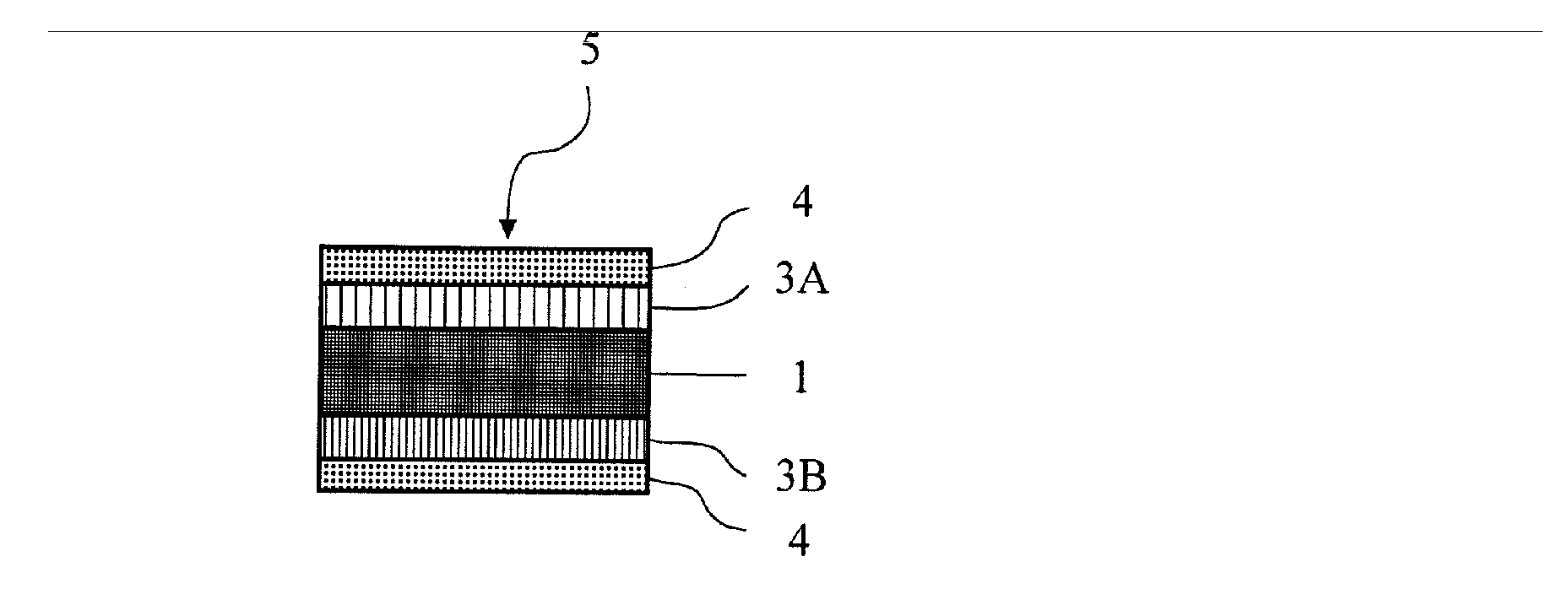
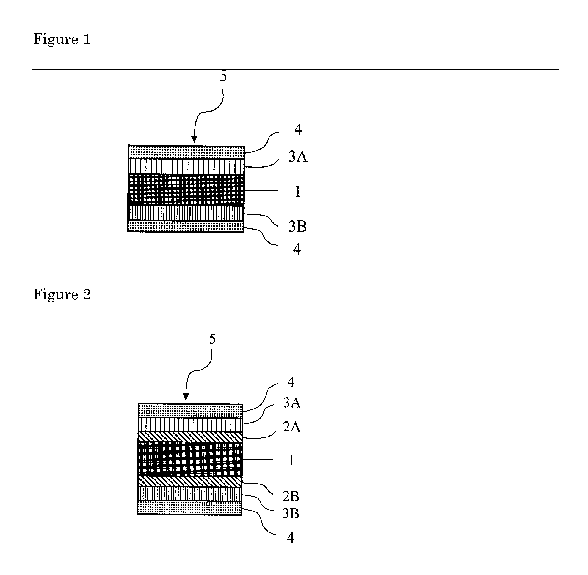
[0013]According to the process for producing an organic EL panel of the present invention, there is no generation of “fractures” and “cuts” in the ultrathin glass plate, for example during conveyance in the production process, because the organic EL element is formed, as an ultrathin glass plate having a thickness of 10 to 150 μm is temporarily bonded to a supporting plate with a particular double-sided adhesive tape. Since the double-sided adhesive tape containing heat-expandable microspheres that starts expansion and / or foaming at a temperature higher than the vacuum deposition temperature is used as the double-sided adhesive tape, there is no offgas generated during production of the organic EL element by vacuum deposition method and it is possible to evacuate the system rapidly into vacuum state and thus to improve the film precision and productivity.
[0014]It is also possible to expand and / or foam the heat-expandable microspheres in the double-sided adhesive tape rapidly by heating at a predetermined temperature after production process, and decrease the adhesion face with the ultrathin glass plate significantly. It is thus possible to separate the ultrathin glass plate easily without fracture thereof and residual of the adhesive, therefore there is no need for cleaning the rear face of the ultrathin glass plate in the organic EL panel after separation. In addition, there is no need for use of an organic solvent or the like, which has been used traditionally in the cleaning step to remove the adhesive residue on the rear face of the substrate, thus eliminating the possibility of problems such as low processability and environmental pollution. The organic EL panel obtained by the process for producing an organic EL panel according to the present invention is higher in flexibility and superior in gas barrier properties, and is thus resistant significantly to growth of so-called dark spots, deterioration in light transmittance, and also drastic decrease in light-emitting efficiency over an extended period of time, and useful as a long-lasting flexible display.

Problems solved by technology

In addition, organic solids used in organic EL elements, such as light-emitting layer (organic emitter), electron, and positive hole transport materials, had a problem that they are generally extremely unstable to water and oxygen, and degraded by water and oxygen present in organic EL element and also by water and oxygen penetrating into the element from outside, leading to growth of so-called dark spots, deterioration in light permeability and thus drastic decrease in luminous efficiency.
However, the ultrathin glass plates are very brittle and, if an ultrathin glass plate is conveyed alone in the production process for forming an organic EL element on the ultrathin glass plate, there is a problem of decrease in yield caused by generation of “fractures” and “cuts” in the ultrathin glass plate during conveyance.
Accordingly, the method has a problem of low maintenance efficiency and low processability.
Alternatively in the case of the substrate-bonding method of conveying the ultrathin glass plate, as it is bonded to a substrate with a wax or bonding agent, an additional step of removing the wax or bonding agent deposited on the rear face of the ultrathin glass plate with organic solvent should be installed after production process, which makes it difficult to improve productivity.
If the thermal release adhesive sheet is used as a sheet for temporary fixation of the ultrathin glass plate, when an organic electroluminescent element is formed on an ultrathin glass plate by vacuum deposition method in the production step for organic EL panels, hydrocarbon gas may be generated in a great amount in the vacuum chamber, causing decrease in the degree of vacuum and elongation of the period needed for the vacuum chamber to reach a desired degree of vacuum, causing a problem of drastic deterioration in film precision and productivity.
In other words, there is currently no available process for producing an organic EL panel superior in flexibility and gas barrier properties by using an ultrathin glass plate, by which it is possible to protect the ultrathin glass plate from generation of “fractures” and “cuts” during conveyance in the production process, to produce the organic EL element efficiently by evacuating the system to a particular degree of vacuum rapidly when an organic EL element is formed by vacuum deposition, and to recover the organic EL panel obtained without damage of the ultrathin glass plate after production process, and in which there is no need for an additional cleaning step of removing the adhesive substance and others deposited on the rear face of the ultrathin glass plate.

Method used


Image

  • Process for producing organic electroluminescent panel
  • Process for producing organic electroluminescent panel

Examples


example 1

[0077]A toluene solution containing 100 wt parts of a pressure-sensitive adhesive based on a copolymer of 2-ethylhexyl acrylate / ethyl acrylate / methyl methacrylate / 2-hydroxyethyl acrylate (30 wt parts / 70 wt parts / 5 wt parts / 5 wt parts) and 1 wt part of an isocyanate-based crosslinking agent blended therein was coated and dried on both faces of a base substance polyester film (thickness: 100 μm) to a thickness of 20 μm after drying, to give rubber-like organic elastic layers A and B.

[0078]Then, a toluene solution containing 100 wt parts of a pressure-sensitive adhesive based on a copolymer of 2-ethylhexyl acrylate / ethyl acrylate / methyl methacrylate / 2-hydroxyethyl acrylate (30 wt parts / 70 wt parts / 5 wt parts / 5 wt parts), 2 wt parts of an isocyanate-based crosslinking agent, and 30 wt parts of heat-expandable microspheres A (trade nameMicrosphere F100D”, produced by Matsumoto Yushi-Seiyaku Co., Ltd., foaming-starting temperature: approximately 170° C.) blended therein was coated and d...

example 2

[0081]A toluene solution containing 100 wt parts of a pressure-sensitive adhesive based on a copolymer of 2-ethylhexyl acrylate / ethyl acrylate / acrylic acid (30 wt parts / 70 wt parts / 5 wt parts) and 2 wt parts of an isocyanate-based crosslinking agent blended therein was coated and dried on both faces of a base substance polyester film (thickness: 100 μm) to a thickness of 20 μm after drying, to give a rubber-like organic elastic layers C and D.

[0082]Then, a toluene solution containing 100 wt parts of a pressure-sensitive adhesive based on a copolymer of 2-ethylhexyl acrylate / ethyl acrylate / acrylic acid (30 wt parts / 70 wt parts / 5 wt parts), 5 wt parts of an isocyanate-based crosslinking agent, and 30 wt parts of heat-expandable microspheres A (trade name: “Microsphere F100D”, produced by Matsumoto Yushi-Seiyaku Co., Ltd., foaming-starting temperature: approximately 170° C.) blended therein was coated and dried on a separator to a thickness of 30 μm, to give a thermal release adhesive ...


PUM

PropertyMeasurementUnit
Temperatureaaaaaaaaaa
Thicknessaaaaaaaaaa
Fractionaaaaaaaaaa

Abstract

Provided is a process for producing an organic EL panel by using an ultrathin glass plate, in which the ultrathin glass plate is not “fractured” or “cut” in the production process, the organic EL element is formed reliably when formed by vacuum deposition, and recovered without damage after the production process, and there is no need for installing an additional step of cleaning the rear face of the ultrathin glass plate. The process for producing an organic EL panel according to the present invention is a process for producing an organic electroluminescent panel by forming an organic electroluminescent element on an ultrathin glass plate by vacuum deposition method, comprising forming electrodes on the ultrathin glass plate, by temporarily fixing the ultrathin glass plate to a supporting plate via a double-sided adhesive tape having a thermal release adhesive layer formed at least on one face of the base material layer, containing heat-expandable microspheres that start expansion and / or foaming at temperature higher than the vacuum deposition temperature.

Description

TECHNICAL FIELD[0001]The present invention relates to a process for producing an organic electroluminescent panel by using a double-sided adhesive tape. The organic electroluminescent panel according to the present invention is very useful as display devices, displays or as various kinds of emission light sources.BACKGROUND ART[0002]Organic electroluminescent elements (hereinafter, an organic electroluminescent may be referred to as “organic EL”) are light-emitting elements in a structure having a light-emitting layer containing a light-emitting compound held between negative and positive electrodes, in which excitons are generated by recombination of electrons and positive holes injected into the light-emitting layer and light (fluorescence or phosphorescence) is emitted when the excitons are inactivated. These elements are attracting attention recently, as they emit light even at a voltage approximately of several to several tens V, and are characteristic of wide view angle and hi...

Claims


Application Information

Patent Timeline
IPC IPC(8): H01L33/00C09J7/38
CPCC08K7/22C09J5/06C09J7/0207C09J2201/128C09J2205/102C09J2205/11Y10T156/1163H01L51/001H01L51/0096H01L51/50H01L2227/326Y10T156/1195C09J2205/302C09J7/38Y02E10/549C09J2301/124C09J2301/408C09J2301/412C09J2301/502Y02P70/50H10K71/164H10K77/10H10K71/80H10K59/1201H10K50/8426H10K71/00C09J5/08H10K71/60H10K50/00
Inventor HIRAYAMA, TAKAMASAMURATA, AKIHISAARIMITSU, YUKIOYAMAOKA, TAKASHISATO, MASAAKI
Owner NITTO DENKO CORP
Learn More