
Vacuum processing apparatus and plasma processing apparatus with temperature control function for wafer stage

a technology of plasma processing and vacuum processing, which is applied in the direction of coating, chemical vapor deposition coating, metallic material coating process, etc., can solve the problems of deteriorating in-plane temperature uniformity, high power consumption that accompanies such an increase in electric power, and high power consumption. , to achieve the effect of low power consumption

Active Publication Date: 2011-06-09
HITACHI HIGH-TECH CORP
View PDF6 Cites 23 Cited by
  • Summary
  • Abstract
  • Description
  • Claims
  • Application Information

AI Technical Summary

Benefits of technology

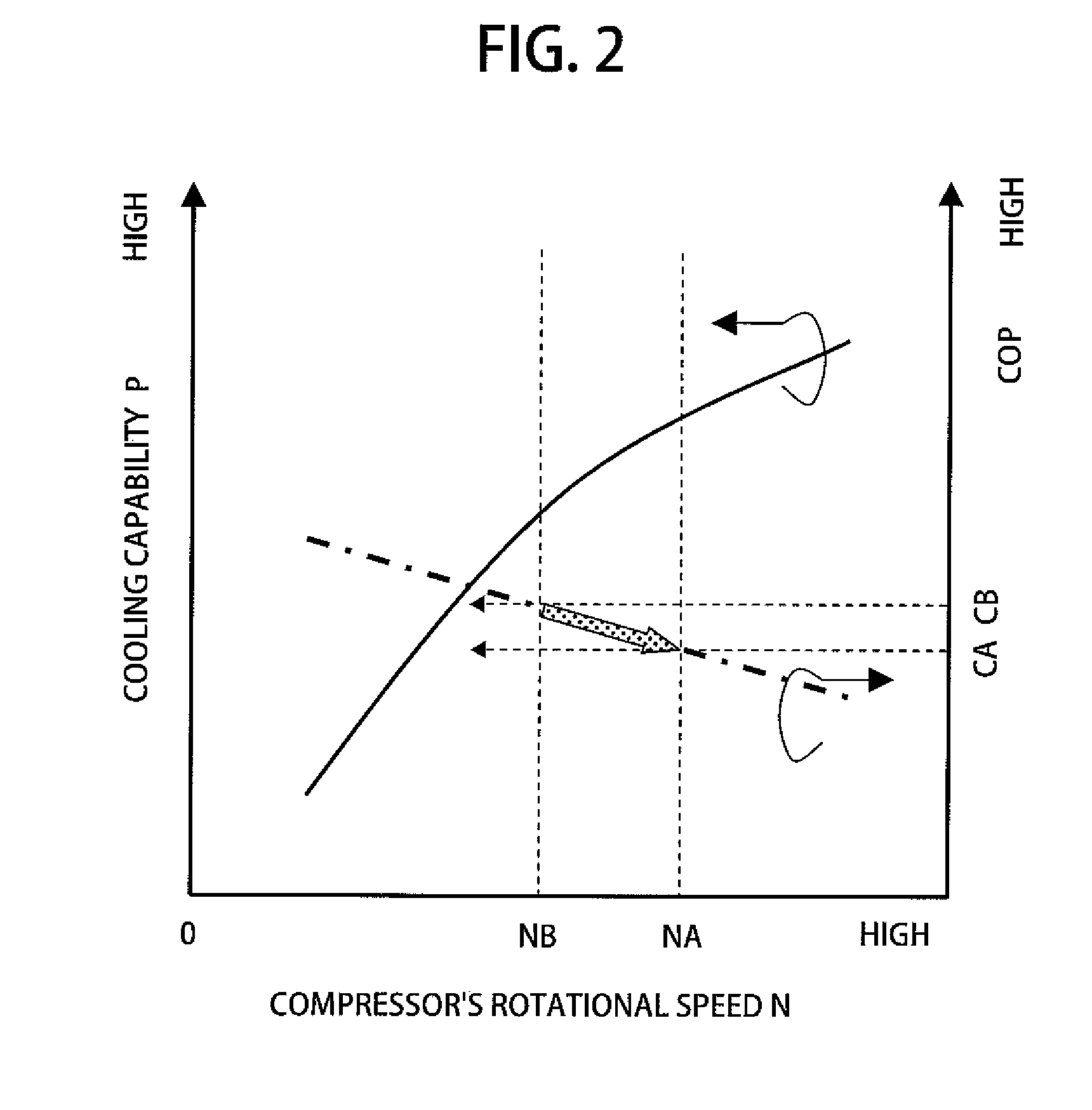
The present invention provides a vacuum processing apparatus and a plasma processing apparatus with a temperature control function for a wafer stage. The apparatuses can improve the coefficient of performance (COP: cooling capability / power consumption) by optimizing the amount of the refrigerant circulating in a cycle of the direct-expansion cooling system. The apparatuses can measure the degree of dryness of the refrigerant discharged from the wafer stage and control the rotational speed of the compressor accordingly to reduce the amount of the refrigerant circulating in the cooling cycle within a range in which dry-out does not occur in the evaporator. This invention helps to achieve uniform in-plane temperature distribution with low power consumption.

Problems solved by technology

However, high power consumption that accompanies such an increase in electric power is a new problem.
If the refrigerant is completely evaporated in the refrigerant passage of the wafer stage in the process of a wafer processing, the wafer stage cannot be uniformly cooled, which deteriorates in-plane temperature uniformity across the wafer stage and of course the wafer surface.
Such a redundant refrigerant supplied to the wafer stage boosts the power consumption of the direct-expansion cooling system.
However, even the method disclosed in Japanese Patent Application Laid-Open Publication No. 2008-187063 cannot quantitatively measure the degree of dryness of the refrigerant discharged from the wafer stage.

Method used


Image

  • Vacuum processing apparatus and plasma processing apparatus with temperature control function for wafer stage
  • Vacuum processing apparatus and plasma processing apparatus with temperature control function for wafer stage
  • Vacuum processing apparatus and plasma processing apparatus with temperature control function for wafer stage

Examples


first embodiment

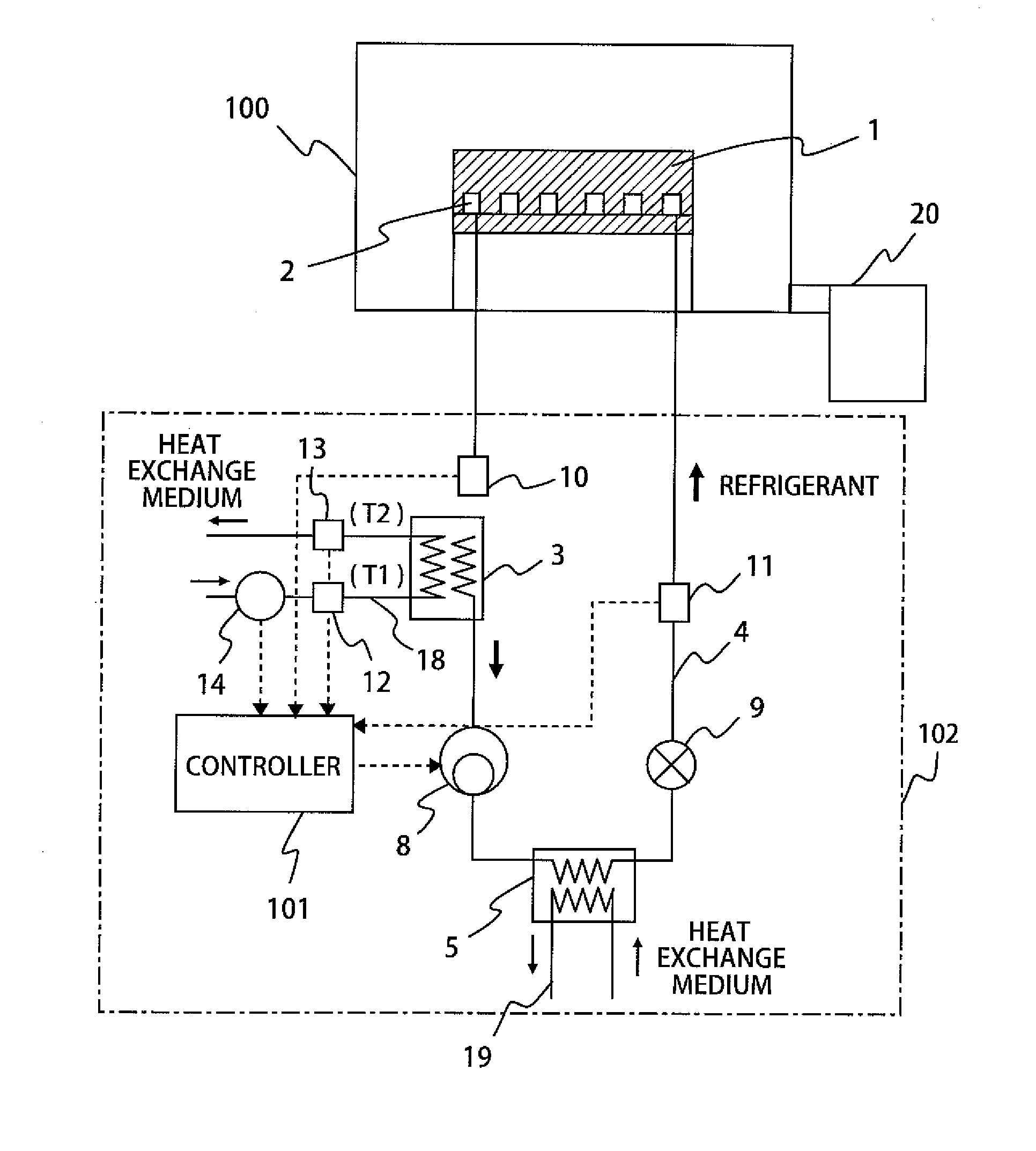
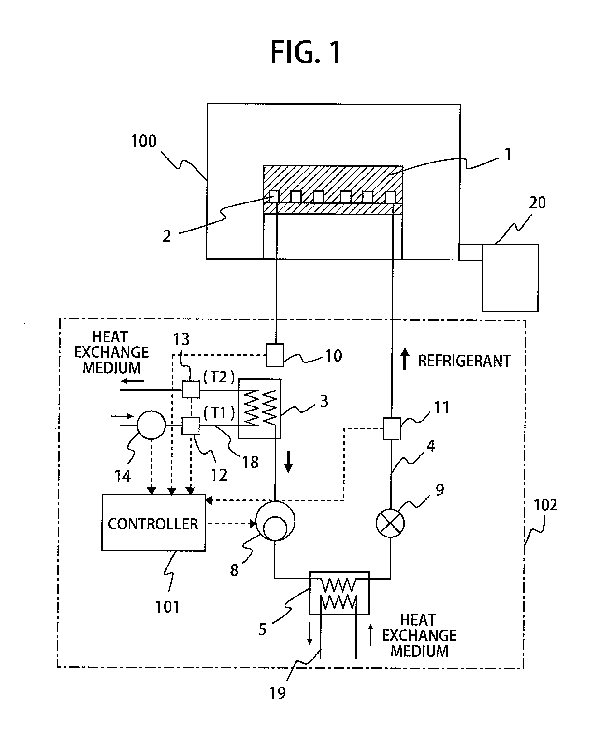
[0033]A vacuum processing apparatus according to a first embodiment of the present invention, and more particularly, an exemplary structure of a plasma processing apparatus will be described below.

[0034]FIG. 1 is a schematic view showing a structure of a direct-expansion cooling system with a dryness measurement function according to the first embodiment of the present invention. The plasma processing apparatus includes a processing chamber 100 placed in a vacuum vessel and a wafer stage 1 placed in the processing chamber 100. The upper surface of the wafer stage has an electrostatic chuck function and is used as a wafer placement surface on which a substrate, such as a wafer, to be subjected to a process is placed. The processing chamber 100 is connected to a vacuum evacuation device 20, such as a vacuum pump, used to evacuate the interior of the processing chamber 100 for pressure reduction.

[0035]The wafer stage 1 is provided with a first evaporator 2 (a refrigerant passage) in wh...

second embodiment

[0049]Next, a second embodiment, which is a modification of the first embodiment, of the present invention will be described. FIG. 4 illustrates an example of a direct-expansion cooling system with a first condenser 5 and second evaporator 3, their coolant (heat exchange medium) passages being connected in series by a heat medium passage 180. A suction tank 15 through which only vapor can pass is connected to a refrigerant passage between the second evaporator 3 and compressor 8, while a reservoir tank 16 through which only liquid can pass is connected to the refrigerant passage between the first condenser 5 and expansion valve 9. This cooling system is controlled by a controller (or control board) 101 using a computer.

[0050]According to the second embodiment, a refrigerant that increases in temperature in the first condenser 5 exchanges heat with a coolant and resultantly raises the temperature (T1) of the coolant, thereby supplying the hot coolant to the second evaporator 3. Becau...

third embodiment

[0053]Next, a vacuum processing apparatus, and more particularly a plasma processing apparatus, according to a third embodiment of the present invention will be described.

[0054]FIG. 5 illustrates a plasma processing apparatus, or, for example an etching apparatus with a temperature control system for a wafer stage, the temperature control system reusing exhaust heat in the etching apparatus. A first evaporator 2 provided in a wafer stage 1 serves as an evaporator in the direct-expansion refrigerator (first cooling system) 102 described in the first and second embodiments and can reduce the temperature of the wafer stage 1 to a low level. In addition to the first evaporator 2, the wafer stage 1 includes a third condenser (wafer-stage condenser) 31. The third condenser 31 is connected to a second condenser 36, a second compressor 38, a second expansion valve 39 and a third evaporator 32 through a second refrigerant passage 30, and these components make up a cooling system (a second co...


PUM

PropertyMeasurementUnit
rotational speedaaaaaaaaaa
temperatureaaaaaaaaaa
temperature distributionaaaaaaaaaa

Abstract

A wafer stage includes a first evaporator where a refrigerant circulates. The first evaporator makes up a cooling cycle with a compressor, first condenser, expansion valve, second evaporator, refrigerant thermometer, and refrigerant flowmeter. The first condenser is supplied with a heat exchange medium. The temperature of a coolant supplied to the second evaporator is measured by an inlet refrigerant thermometer and outlet refrigerant thermometer, while the flow rate of the coolant is monitored and adjusted by a flow-rate adjuster. The temperature difference in the coolant between being at the inlet and at the outlet and flow rate can be measured. Upon complete evaporation of the refrigerant in the second evaporator, the dryness of the refrigerant discharged from the wafer stage is calculated from the amount of heat absorbed from (exchanged with) the coolant, the circulation amount of the refrigerant and the refrigerant temperature to control the rotational speed of the compressor.

Description

CLAIM OF PRIORITY[0001]The present application claims priority from Japanese Patent Application JP 2009-276499 filed on Dec. 4, 2009, the contents of which are hereby incorporated by reference into this application.FIELD OF THE INVENTION[0002]The present invention relates to a vacuum processing apparatus and a plasma processing apparatus with a function of controlling the temperature of a wafer stage, and more particularly, to a wafer-stage temperature control device suitable for a plasma processing apparatus that carries out microfabrication processes on a sample, such as a wafer, with high accuracy.BACKGROUND OF THE INVENTION[0003]Along with the microfabrication of a semiconductor device, processing accuracy required for an etching process of a wafer has been increasingly strict year after year. In order to perform a highly accurate process for finely patterning a wafer surface with a plasma processing apparatus, it is important to control the temperature of the wafer surface duri...

Claims


Application Information

Patent Timeline
Patent Type & Authority Applications(United States)
IPC IPC(8): H01L21/465
CPCH01L21/67109H01L21/67017
Inventor TANDOU, TAKUMIIZAWA, MASARU
Owner HITACHI HIGH-TECH CORP
Learn More