
Magnetic Probe Apparatus

a probe and magnetic technology, applied in the field of magnetic probe apparatus, can solve the problems of difficult positioning of sentinel nodes during surgery, high cost, logistical burden, etc., and achieve the effect of reducing heat conduction

Active Publication Date: 2011-06-09
ENDOMAGNETICS LTD
View PDF103 Cites 43 Cited by
  • Summary
  • Abstract
  • Description
  • Claims
  • Application Information

AI Technical Summary

Benefits of technology

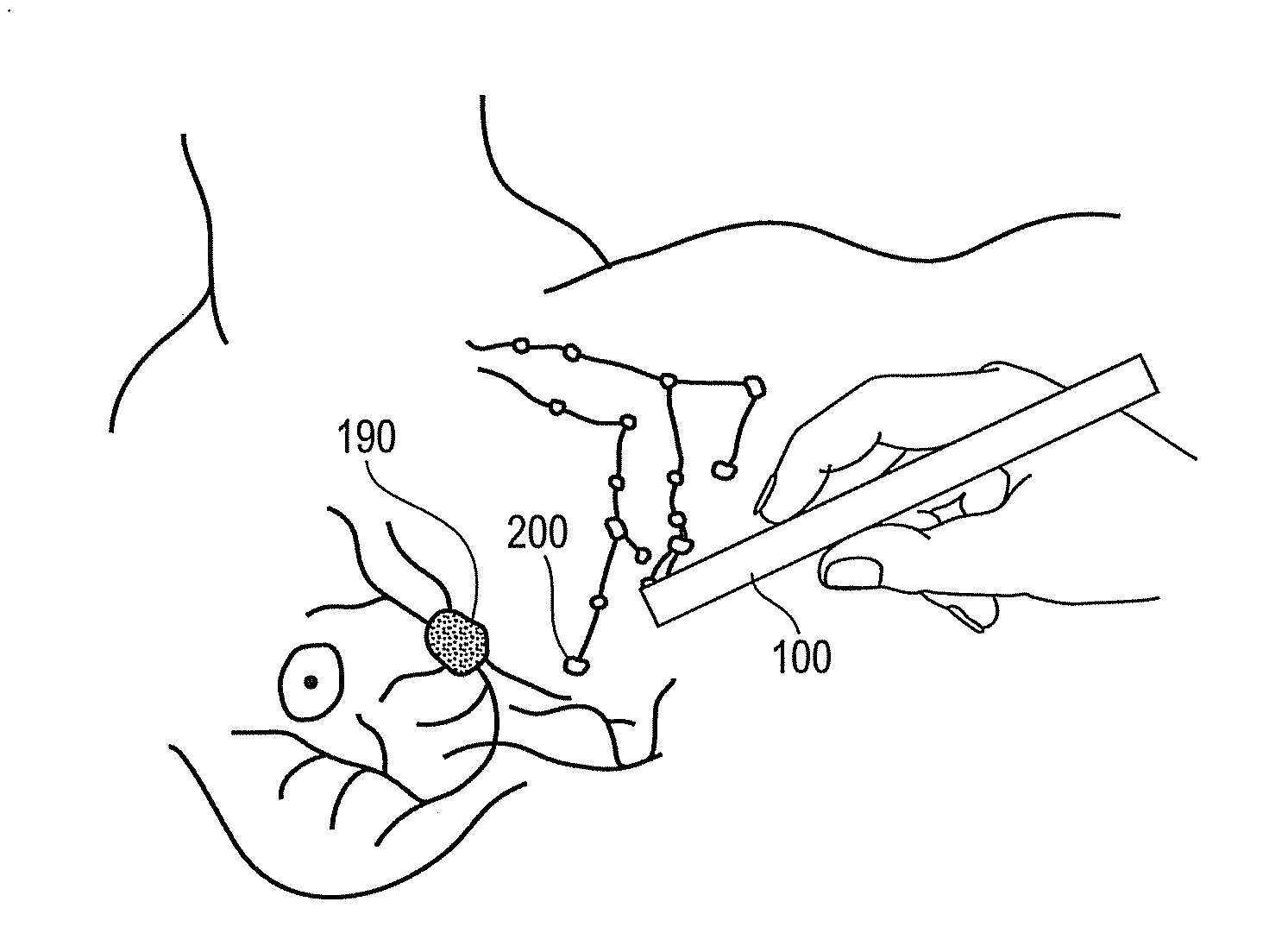
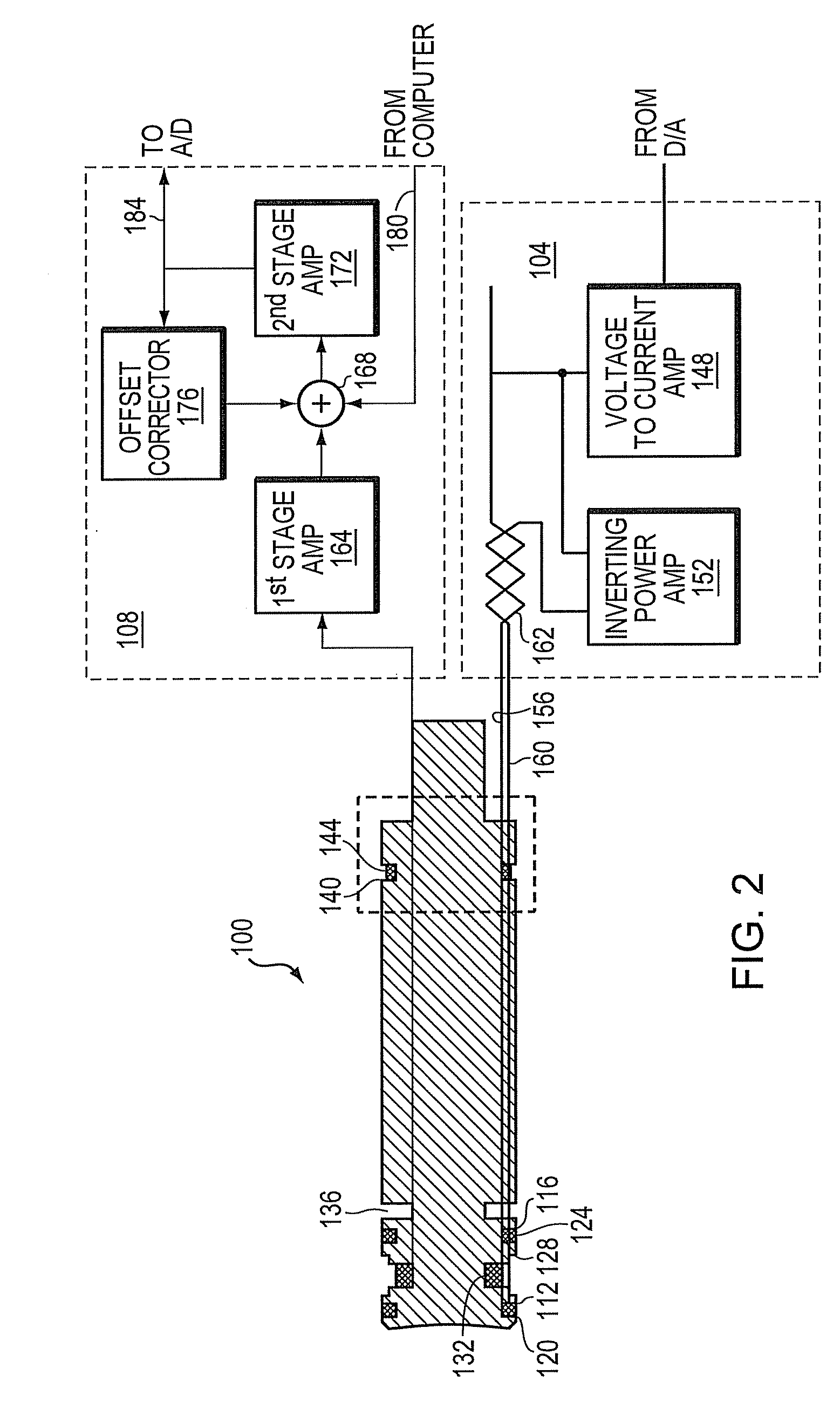
[0012]In one embodiment the magnetic probe further comprises an optional sense coil positioned away from the drive coils and constructed so as to cancel ambient magnetic field effects in the sense coil. In another embodiment the probe is cylindrical and the drive and sense coils are positioned within respective circumferential grooves in the cylindrical magnetic probe. In yet another embodiment an additional circumferential groove is constructed in the cylinder to reduce heat conduction.

Problems solved by technology

Locating sentinel nodes during surgery is difficult.
This method is recognized as being error-prone.
However, the use of radioisotopes presents a significant, and an expensive, logistical burden, because of the need to allocate the time and resources of a nuclear medicine radiologist in addition to the surgeon for what is otherwise a routine operation.
Further many patients are reluctant to receive a radioactive injection.
These factors become a significant barrier to the widespread adoption of the use of radioisotopes to locate the sentinel nodes.

Method used


Image

  • Magnetic Probe Apparatus
  • Magnetic Probe Apparatus
  • Magnetic Probe Apparatus

Examples


Embodiment Construction

[0025]The following description refers to the accompanying drawings that illustrate certain embodiments of the invention. Other embodiments are possible and modifications may be made to the embodiments without departing from the spirit and scope of the invention. Therefore, the following detailed description is not meant to limit the invention. Rather, the scope of the invention is defined by the appended claims.

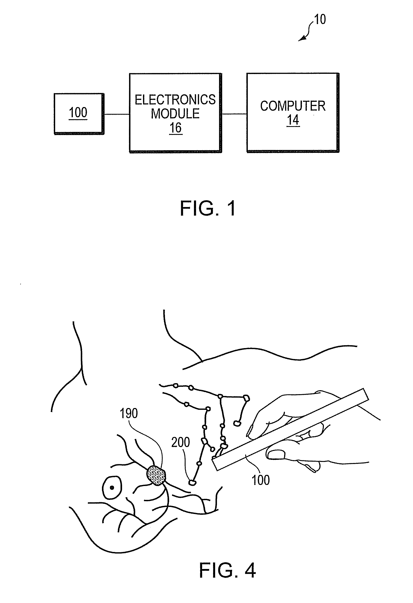
[0026]Referring to FIG. 1, in brief overview, a system 10 constructed in accordance with the teachings of the invention includes a computer 14 having a processor, RAM memory, long term data storage, input / output devices and display; an electronic module 16 containing the power and sensor electronics for the probe and the probe itself 100. In one embodiment the input / output devices include a digital to analog converter and an analog to digital converter.

[0027]To maintain the stability of the system, it is necessary in part to provide thermal stability in the probe. This is do...


PUM

PropertyMeasurementUnit
Young's modulusaaaaaaaaaa
diameteraaaaaaaaaa
diameteraaaaaaaaaa

Abstract

A system and method for locating magnetic material. In one embodiment the system includes a magnetic probe; a power module in electrical communication with the magnetic probe to supply current to the magnetic probe; a sense module in electrical communication with the magnetic probe to receive signals from the magnetic probe; and a computer in electrical communication with the power module and the sense module. The computer generates a waveform that controls the supply of current from the power module and receives a signal from the sense module that indicates the presence of magnetic material. The magnetic probe is constructed from a material having a coefficient of thermal expansion of substantially 10−6 / ° C. or less and a Young's modulus of substantially 50 GPa or greater. In one embodiment magnetic nanoparticles are injected into a breast and the lymph nodes collecting the particles are detected with the probe and deemed sentinel nodes.

Description

FIELD OF INVENTION[0001]This invention relates to the field of medical diagnostic devices and more specifically to a device to detect tissues of interest during a surgical procedure.BACKGROUND[0002]Approximately 1.25 million new cases of breast cancer are diagnosed each year. In a majority of these cases, there is an urgent need for surgery to remove the tumor and to excise the sentinel lymph nodes and inspect them histologically to determine whether the cancer has spread to other sites in the body. The sentinel lymph nodes are the first nodes to receive lymphatic drainage from the tumor. They are called this because they reliably alert the clinician to any cancer spread. A sentinel lymph node biopsy is a standard of care in breast cancer operations today.[0003]Locating sentinel nodes during surgery is difficult. One method for locating the sentinel node is to inject a dark blue dye into the lymphatic system in the breast. The dye then disperses throughout the breast lymphatic syste...

Claims


Application Information

Patent Timeline
Patent Type & Authority Applications(United States)
IPC IPC(8): G01R33/12
CPCA61B5/05A61B5/065A61B5/415A61B5/418G01R33/1269A61B2562/12A61K49/1863B82Y5/00A61B5/4312A61B2017/00876
Inventor HATTERSLEY, SIMON RICHARD
Owner ENDOMAGNETICS LTD
Learn More