Image processing method, image processing apparatus, and image pickup apparatus for correcting degradation component of image

a technology of image processing and component, applied in image enhancement, instruments, computing, etc., can solve the problems of inability to obtain image worth viewing, inability to achieve image worth viewing, and remarkably amplified disadvantages of noise components, so as to reduce the phase degradation component of the image

Active Publication Date: 2011-06-09
CANON KK
View PDF6 Cites 50 Cited by
  • Summary
  • Abstract
  • Description
  • Claims
  • Application Information

AI Technical Summary

Benefits of technology

[0033]An image processing method according to the present invention includes the steps of obtaining an image generated by an image pickup system, and performing correction processing for the image by utilizing an image restoration filter generated or selected based on an optical transfer function of the image pickup system. The image restoration filter is a filter configured to reduce a phase degradation component of the image.
[0034]An image processing apparatus according to the present invention configured to process an image generated by an image pickup system, the image processing apparatus includes a correction unit configured to perform correction processing for the image by utilizing an image restoration filter generated or selected based on an optical transfer function of the image pickup system. The image restoration filter is a filter configured to reduce a phase degradation component of the image.

Problems solved by technology

The real image has a noise component, and the noise component is remarkably amplified disadvantageously along with the restoration of the deteriorated image when the restoration utilizes the image restoration filter made with a perfect reciprocal of the OTF.
With noises, an image worth viewing cannot generally be obtained.
In addition, when there is a difference between the aberrational characteristic in the actual image pickup condition and the aberrational characteristic estimated by the image restoration filter, the restored image may contain a problem of an artifact, such as ringing.
Nevertheless, this method cannot correct the phase component (PTF) of the aberration or the asymmetry, such as the coma and the lateral chromatic aberration.
The edge enhancement cannot correct the deletion of the image in the periphery of the image.
The lateral chromatic aberration correcting method disclosed in JP 06-113309 can correct the color shift caused by the positional shifts among the chromatic components of the PSF, but cannot correct the asymmetry of the PSF itself for each chromatic component since this method is directed to the shift conversion of the image position.
Thus, the correction that equalizes the image magnifications among the chromatic components so as to make inconspicuous the color shift at the edge cannot optimize both the side close to the optical axis and the side far from the optical axis since the color shifts are different between both sides.

Method used


Image

  • Image processing method, image processing apparatus, and image pickup apparatus for correcting degradation component of image
  • Image processing method, image processing apparatus, and image pickup apparatus for correcting degradation component of image
  • Image processing method, image processing apparatus, and image pickup apparatus for correcting degradation component of image

Examples


embodiment 1

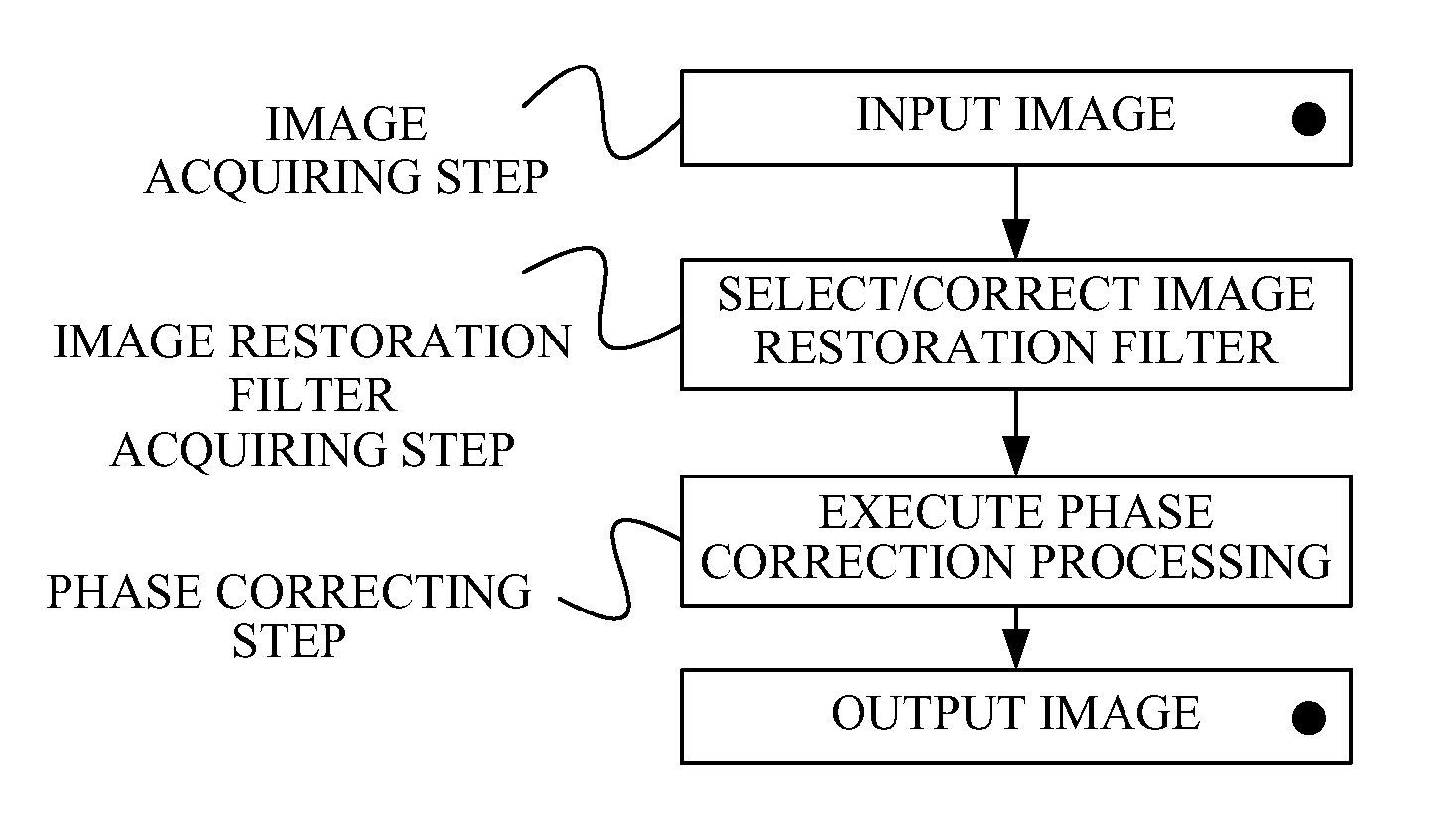
[0101]FIG. 7 illustrates a basic configuration of an image pickup apparatus including an image processing apparatus according to Embodiment 1 of the present invention.

[0102]An image pickup optical system 101 forms an object image on an image pickup device 102 by utilizing light from an object (not illustrated). The image pickup device 102 converts the object image into an electric signal. The electric signal (analogue signal) output from the image pickup device 102 is converted into digital image data through an A / D converter 103, and input to an image processor 104.

[0103]The image processor 104 performs a variety of image processing and the correction processing of the phase (degradation) component for input digital image data (input image). Initially, the image processor 104 obtains from a condition detector 107 image pickup condition information (a condition of the optical system) that is information representing a condition of the image pickup optical system 101 (such as a focal...

embodiment 2

[0128]A description will now be given of an image processing method according to Embodiment 2 of the present invention. This image processing method is executed by an image processor (image processing apparatus) of an image pickup apparatus having a structure similar to that of the image pickup apparatus described in the Embodiment 1.

[0129]This embodiment extracts an aberrational component of an input image, controls a removal amount of this aberration component, and thereby adjusts the restoration degree. When the restoration degree is adjusted, the asymmetry of the aberration among the aberrational components does not vary and only a blur amount varies.

[0130]FIG. 11 illustrates a flow of the image processing method executed in this embodiment. In the following description, a sign “m” denotes a chromatic component of an image (such as R, G, and B). For instance, Am denotes (AR, AG, AB) which denotes an R element of A, a G element of A, and a B element of A, respectively. “A” corres...

embodiment 3

[0172]In this embodiment, a description will be given of an image processing method configured to further restrain a generation of the false color associated with the image restoration processing. FIG. 15 is a process flow for generating color composition restoration component information Sdm for each chromatic component by chromatically composing restoration component information Sm for each chromatic component according to a color composition ratio adjustment factor ω, and for composing the color composition restoration component information Sdm with the second image Sm.

[0173]The color composition ratio adjustment factor ω is a mixture ratio of the chromatic components or a factor used to chromatically compose the restoration component information Sm for each of all chromatic components in accordance with the color composition ratio adjustment factor ω and to generate the color composition restoration component information Sdm. Thus, Equation 9 or Equation 10 that develops Equatio...


PUM


Abstract

An image processing method includes the steps of obtaining an image generated by an image pickup system, and performing correction processing for the image by utilizing an image restoration filter generated or selected based on an optical transfer function of the image pickup system. The image restoration filter is a filter configured to reduce a phase degradation component of the image.

Description

BACKGROUND OF THE INVENTION[0001]1. Field of the Invention[0002]The present invention relates to image processing for correcting (or reducing) a deterioration component of an image generated by image pickup, utilizing an image restoration filter.[0003]2. Description of the Related Art[0004]An image obtained by capturing an object by an image pickup apparatus, such as a digital camera, contains a blur component as an image deterioration component, such as the spherical aberration, coma, curvature of field, and astigmatism of an image pickup optical system (simply referred to as an “optical system” hereinafter). This blur occurs when a light flux emitted from one point of the object, which is expected to converge on one point on an image pickup surface when there is no aberration or diffraction, forms an image with some divergence.[0005]The blur, as used herein, is optically represented by a point spread function (“PSF”) and is different from a blur caused by defocusing. A color shift...

Claims


Application Information

Patent Timeline
Patent Type & Authority Applications(United States)
IPC IPC(8): G06K9/40
CPCG06T5/20G06T5/003
Inventor HATAKEYAMA, KOSHI
Owner CANON KK
Why Eureka
Try Eureka