

Apparatus and method for estimating data relating to a time difference and apparatus and method for calibrating a delay line
- Summary
- Abstract
- Description
- Claims
- Application Information
AI Technical Summary
Benefits of technology
Problems solved by technology
Method used
Image

Examples
Embodiment Construction
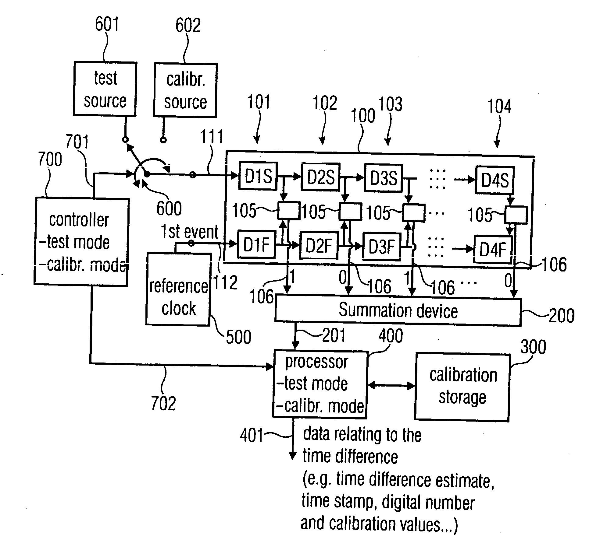
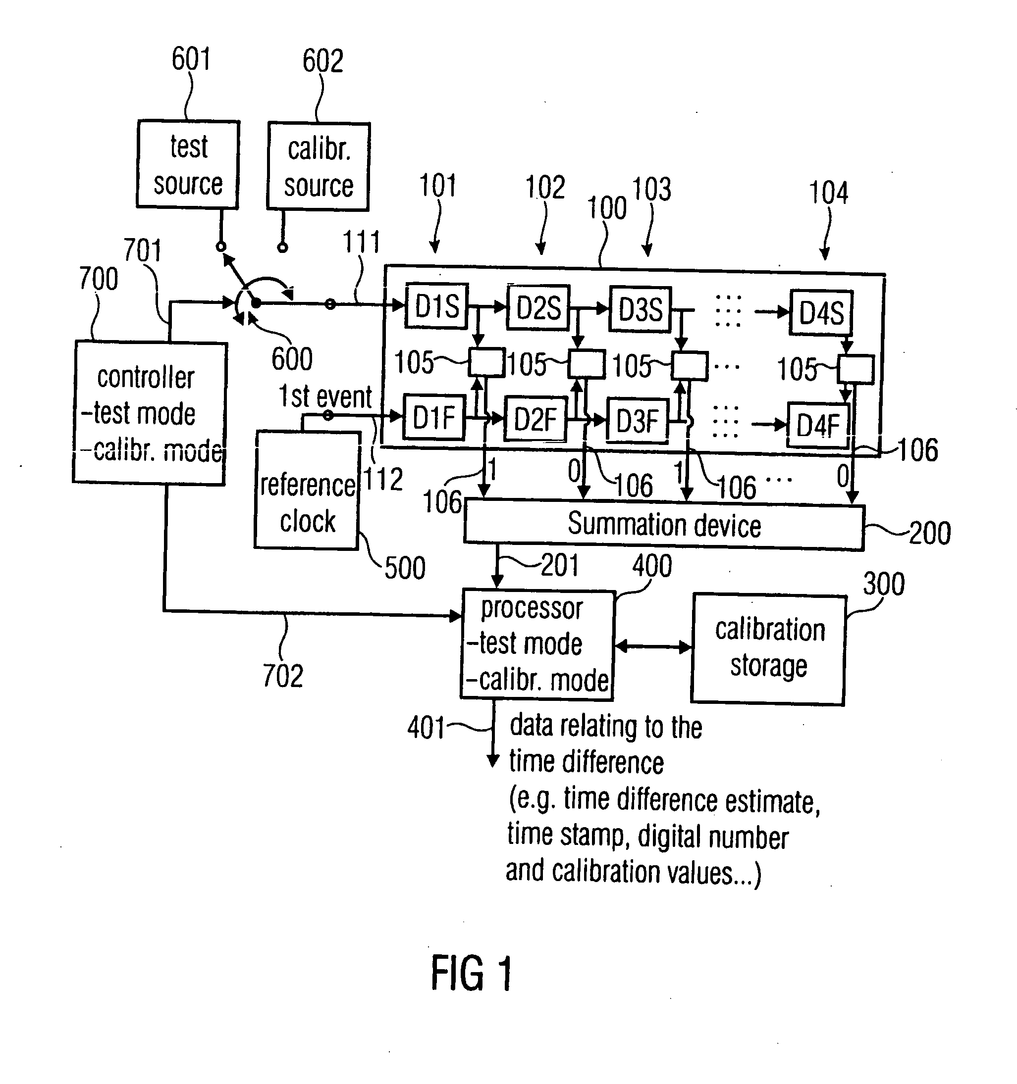
[0042]FIG. 1 illustrates an apparatus for estimating data relating to a time difference between two events. An exemplary time difference between two events is indicated in FIG. 8 where there is a first input into the time to digital convertex or, specifically, into a delay line not illustrated in FIG. 8 and in which a second input into the TDC (Delay Line) is indicated as well. The first input is connected to a test signal having a test signal edge indicated as “event” in FIG. 8. The second event is represented by a rising edge of a clock signal connected to the second input (CLK) of the TDC. The test clock has a period of R and the TDC measures the distance t as indicated in FIG. 8. Thus, the complete time stamp output by the TDC in FIG. 8 is equal to N×R−t. Depending on different applications of the present invention, one input into the TCC need not necessarily be a clock, i.e. the reference clock of the automatic test equipment, but the input can also be another test edge when th...
PUM
 Abstract
Description
Claims
Application Information