Conversion of a Discrete Time Quantized Signal into a Continuous Time, Continuously Variable Signal

a discrete time, continuous time technology, applied in the direction of digital-analog convertors, transmission systems, instruments, etc., can solve the problems of inability to achieve continuous time continuous variable signals, etc., to achieve the effect of overcompensating resolution limitations

Active Publication Date: 2011-06-16
PAGNANELLI FAMILY TRUST
View PDF4 Cites 30 Cited by
  • Summary
  • Abstract
  • Description
  • Claims
  • Application Information

AI Technical Summary

Benefits of technology

[0012]The present invention provides an improved DAC, particularly for use at very high sample rates and instantaneous bandwidths approaching the Nyquist limit. The improved DAC overcomes the resolution limitations of conventional Nyquist converters and the bandwidth limitations of conventional oversampling converters.

Problems solved by technology

Existing solutions are limited by instantaneous bandwidth (sample rate), effective conversion resolution (accuracy), or both.
When a discrete-time discretely variable (digital) signal is converted into a continuous-time continuously variable (analog) signal, the quality of the analog signal is corrupted by various limitations and errors introduced during the conversion process.
However, high-resolution conversion (of ≧10 bits) conventionally has been limited to instantaneous bandwidths of about a few gigahertz (GHz) or less.
Conventional Nyquist converters potentially can achieve very high instantaneous bandwidths, but as discussed in greater detail below, the present inventor has discovered that component mismatches in the resistor ladder network, or in the switched current sources, can introduce rounding errors that significantly limit attainable resolution.
In addition, the resolution of conventional Nyquist converters is limited by other practical implementation impairments such as sampling jitter and thermal noise.
Although Nyquist converters potentially could realize high resolution at instantaneous bandwidths greater than 10 GHz in theory, due to the foregoing problems, this potential has been unrealized in conventional Nyquist converters.
These disadvantages, which are discussed in greater detail in the Description of the Preferred Embodiment(s) section, include: (1) conversion bandwidth that is limited by the narrow low-pass or narrow bandpass filtering operations used to attenuate shaped quantization noise and errors, (2) resolution (SNDR) that is limited by the clock frequency fCLK of the delta-sigma modulator (i.e., the clock frequency of a two-level quantizer), and (3) resolution that is limited by the low-order noise-shaped response (i.e., generally second-order for bandpass modulators) needed for stable operation with two-level quantizers.
Because of these disadvantages, the resolution of conventional oversampling converters cannot be increased without: (1) reducing bandwidth to improve the quantization noise attenuation of the output (smoothing) filters, or (2) increasing the converter sample rate by using higher-speed circuits since high-order modulators are unstable with two-level quantization.
In addition, conventional oversampling converters employ delta-sigma modulator structures that do not provide a means of dynamically varying, or re-programming, the frequency (fnotch) at which the quantization noise frequency response is a minimum.

Method used


Image

  • Conversion of a Discrete Time Quantized Signal into a Continuous Time, Continuously Variable Signal
  • Conversion of a Discrete Time Quantized Signal into a Continuous Time, Continuously Variable Signal
  • Conversion of a Discrete Time Quantized Signal into a Continuous Time, Continuously Variable Signal

Examples


Embodiment Construction

)

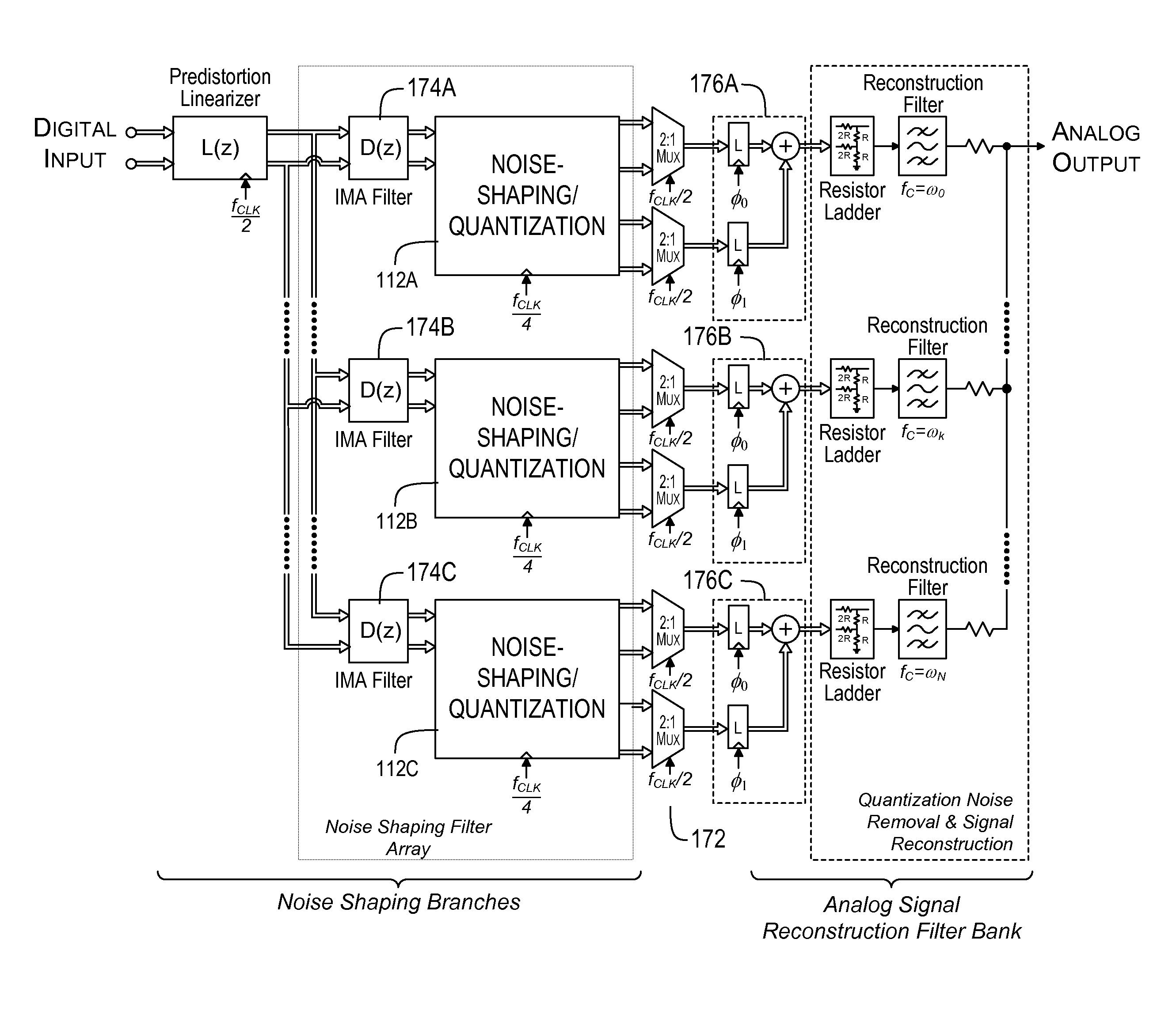
[0034]A preferred converter according to the present invention uses a technique that sometimes is referred to herein as Multi-Channel Bandpass Oversampling (MBO). In a somewhat comparable manner to conventional, oversampling digital-to-analog converters, the MBO converter employs a form of “oversampling” (as that term is broadly used herein) in conjunction with noise shaping to mitigate the resolution-degrading effects of quantization error, sampling jitter, and thermal noise. An MBO converter according to the preferred embodiments of the present invention incorporates one or more of the following technological innovations to improve instantaneous bandwidth and resolution: (1) multiple oversampling converters (e.g., each processing a different frequency band), are operated in parallel to overcome the bandwidth limitations of conventional oversampling converters; (2) multirate (i.e., polyphase) delta-sigma modulators (preferably second-order or higher) are used in place of conventio...


PUM


Abstract

Provided are, among other things, systems, apparatuses, methods and techniques for converting a discrete-time quantized signal into a continuous-time, continuously variable signal. An exemplary converter preferably includes: (1) multiple oversampling converters, each processing a different frequency band, operated in parallel; (2) multirate (i.e., polyphase) delta-sigma modulators (preferably second-order or higher); (3) multi-bit quantizers; (4) multi-bit-to-variable-level signal converters, such as resistor ladder networks or current source networks; (5) adaptive non-linear, bit-mapping to compensate for mismatches in the multi-bit-to-variable-level signal converters (e.g., by mimicking such mismatches and then shifting the resulting noise to a frequently range where it will be filtered out by a corresponding bandpass (reconstruction) filter); (6) multi-band (e.g., programmable noise-transfer-function response) bandpass delta-sigma modulators; and/or (7) a digital pre-distortion linearizer (DPL) for canceling noise and distortion introduced by an analog signal bandpass (reconstruction) filter bank.

Description

[0001]This application claims the benefit of U.S. Provisional Patent Application Ser. No. 61 / 287,079, filed on Dec. 16, 2009, and titled “Method of Discrete to Linear Signal Transformation using Orthogonal Bandpass Oversampling (OBO)”, which application is incorporated by reference herein as though set forth herein in full.FIELD OF THE INVENTION[0002]The present invention pertains to systems, methods and techniques for converting a sampled, quantized (discrete-time) signal into a continuous-time continuously variable (linear) signal. It is particularly applicable to very high sample-rate converters with high instantaneous bandwidth.BACKGROUND[0003]Many applications in modern electronics require that discrete-time signals, generated using computers and digital signal processors, be converted to linear (analog) signals, e.g., for transmission as electromagnetic signals. Typically, this transformation is made using a conventional digital-to-analog converter (DAC). However, the present ...

Claims


Application Information

Patent Timeline
Patent Type & Authority Applications(United States)
IPC IPC(8): H03M1/66
CPCH03M3/358H03M3/502H03M3/50H03M7/3033H03M7/3026
Inventor PAGNANELLI, CHRISTOPHER
Owner PAGNANELLI FAMILY TRUST
Why Eureka
Try Eureka