

Ytterbium-doped optical fiber, fiber laser and fiber amplifier
a technology of ytterbium-doped optical fibers and fiber lasers, which is applied in the direction of optical fibres with polarisation, glass optical fibres, instruments, etc., can solve the problems of easy induced non-linear optical phenomena, limited amplified power during light propagation, and damage to the core glass due to light, etc., to achieve superior optical amplifying effect, reduce the cost of optical fibers, and suppress photodarkening
- Summary
- Abstract
- Description
- Claims
- Application Information
AI Technical Summary
Benefits of technology
Problems solved by technology
Method used
Image

Examples
example 1
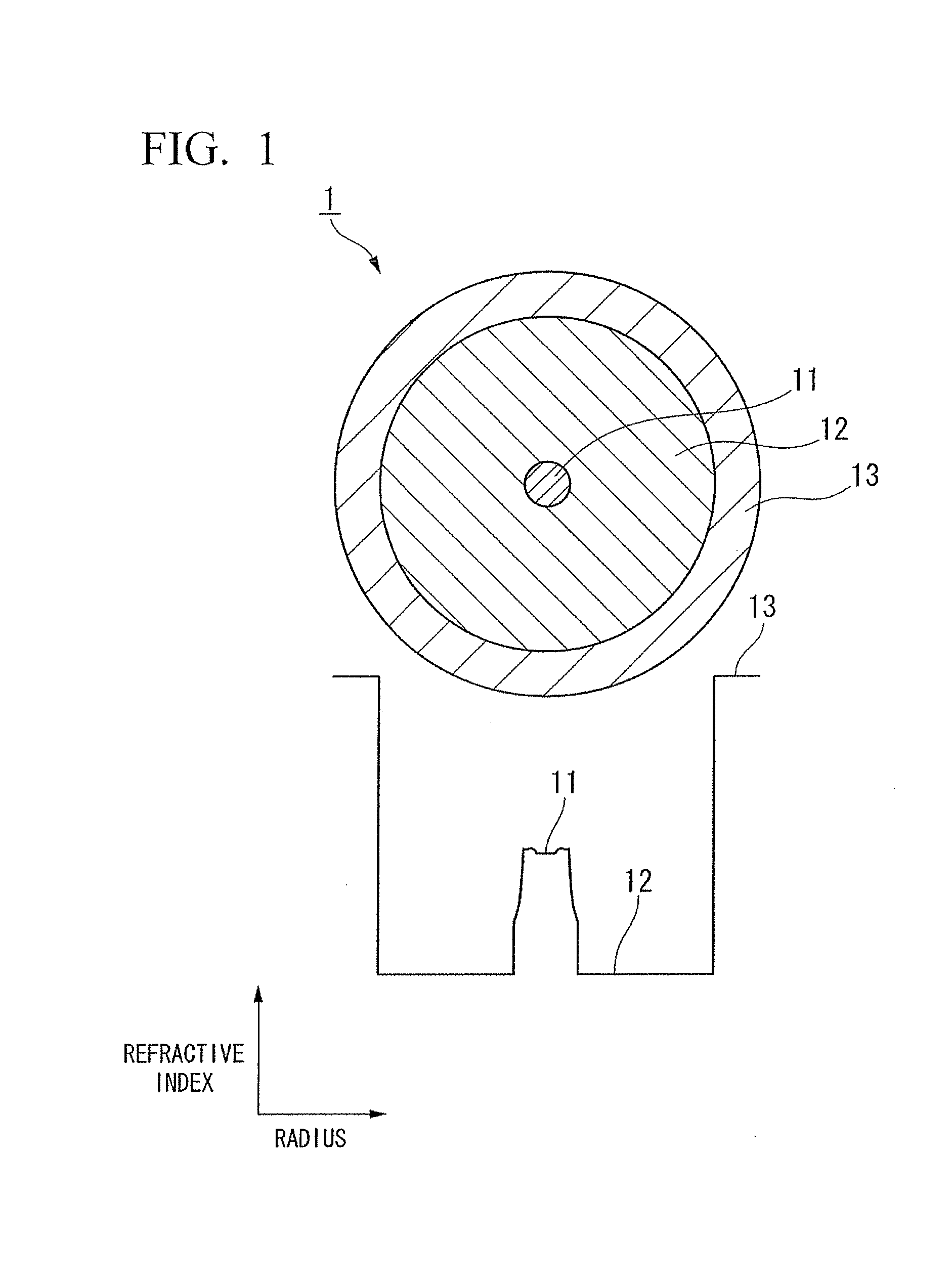
[0093]An Yb-doped optical fiber having the structure shown in FIG. 1 was prepared. FIG. 1 shows a refractive index profile and a cross section in the radial direction of an Yb-doped optical fiber 1. The Yb-doped optical fiber 1 is a single cladding fiber. Cladding 12 is provided on an outer circumference of a core 11, and a protective coating layer 13 is provided on an outer circumference of the cladding 12.
[0094]A fiber preform was prepared using MCVD method. The then Yb is doped using solution method. The fiber preform was then drawn until the outer diameter of the glass was approximately 125 μm, and a protective coating layer was then provided on the outer circumference thereof.
[0095]1.67 mol % of Al2O3 was contained in the core. In the same way, 0.54 mol % of Yb2O3 and 8.37 mol % of P2O5 were also contained in the core. The diameter of the core was approximately 4.9 μm, and the relative refractive index difference (Δ) of the core was approximately 0.64%.
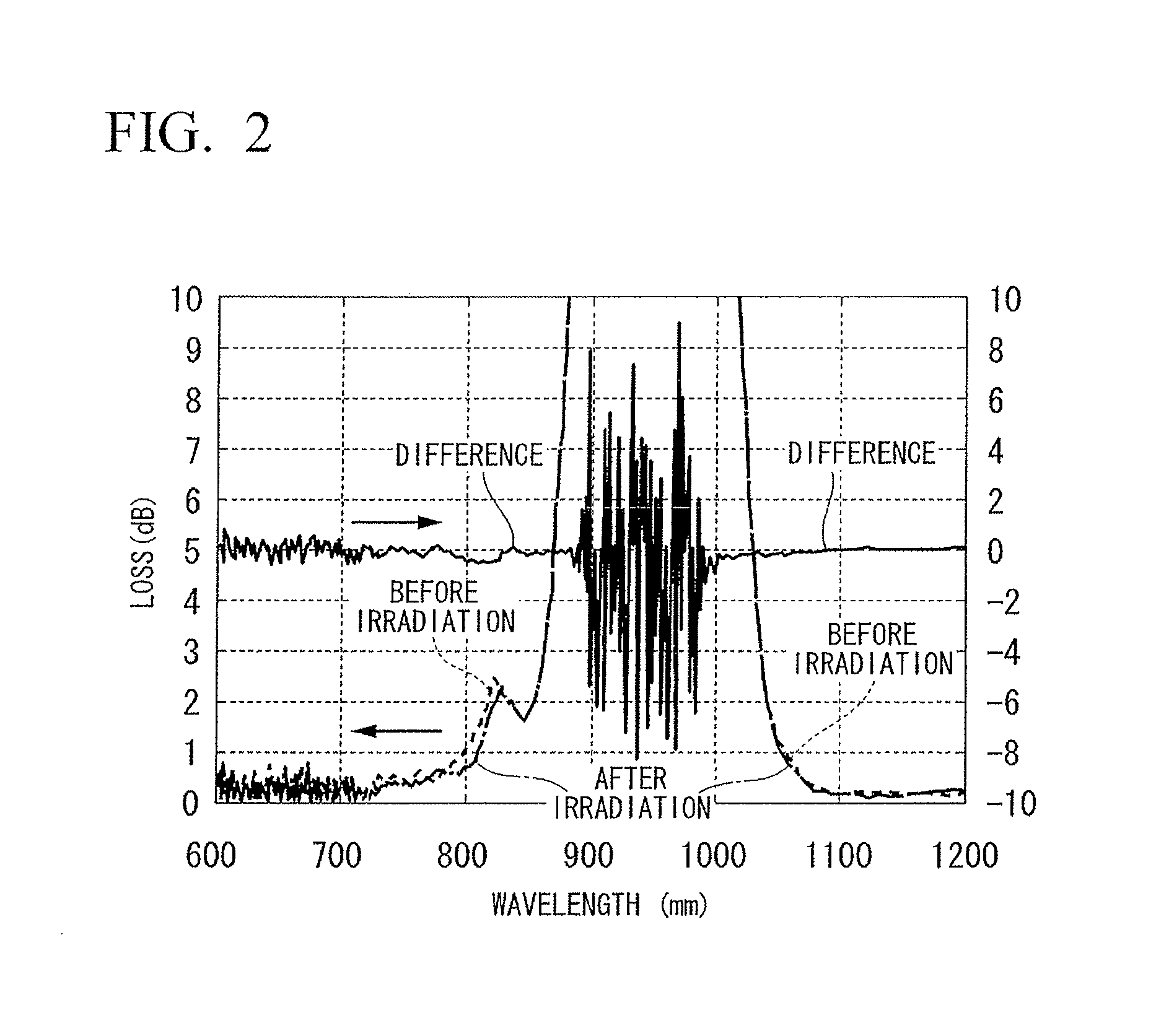
[0096]There was substanti...
example 2
[0099]An Yb-doped optical fiber having the structure shown in FIG. 3 was prepared. FIG. 3 shows a refractive index profile and a cross section in the radial direction of an Yb-doped optical fiber 2. The Yb-doped optical fiber 2 is a single cladding fiber.
[0100]Cladding 22 is provided on an outer circumference of a core 21, and a protective coating layer 23 is provided on an outer circumference of the cladding 22.
[0101]A fiber preform was prepared using VAD method. The Yb is doped using solution method. The fiber preform was then drawn until the outer diameter of the glass was approximately 125 μm, and a protective coating layer was then provided on the outer circumference thereof.
[0102]0.84 mol % of Al2O3 was contained in the core. In the same way, 0.15 mol % of Yb2O3 and 3.85 mol % of P2O5 were also contained in the core. The diameter of the core was approximately 7 μm, and the relative refractive index difference (Δ) of the core was approximately 0.25%.
[0103]There was substantiall...
example 3
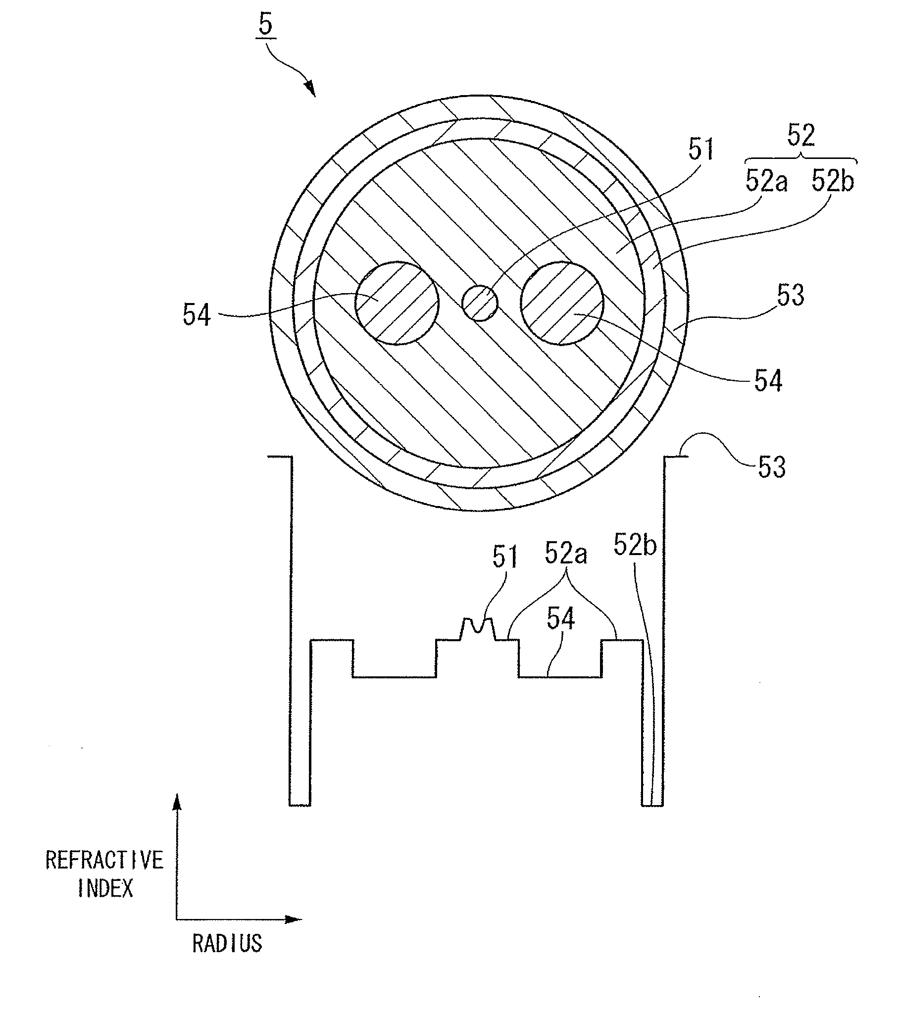
[0106]An Yb-doped optical fiber having the structure shown in FIG. 4 was prepared. FIG. 4 shows a refractive index profile and a cross section in the radial direction of an Yb-doped optical fiber 3. The Yb-doped optical fiber 3 is a single cladding fiber having a core 31 which has a three-layer structure. Cladding 32 is provided on an outer circumference of the core 31, and a protective coating layer 33 is provided on an outer circumference of the cladding 32. The core 31 consists of center core 31a, a ring groove 31b which is provided on an outer circumference of the center core 31a, and a ring core 31c which is provided on an outer circumference of the ring groove 31b.
[0107]A fiber preform was prepared using MCVD method. The Yb is doped using solution method. The fiber preform was then drawn until the outer diameter of the glass was approximately 125 μm, and a protective coating layer was then provided on the outer circumference thereof.
[0108]0.80 mol % of Al2O3 was contained in ...
PUM
| Property | Measurement | Unit |
|---|---|---|
| Fraction | aaaaa | aaaaa |
| Fraction | aaaaa | aaaaa |
| Concentration | aaaaa | aaaaa |
Abstract
Description
Claims
Application Information