Tension-Resistant Electrical Conductor

a technology of electrical conductors and resistive coatings, applied in the direction of flexible conductors, plastic/resin/waxes insulators, organic insulators, etc., can solve the problems of reduced flexibility and corrosion of conductors, and achieve good and lasting electrical contact connections, greater tensile strength, and good tensile strength

Inactive Publication Date: 2011-06-23
HEW KABEL
View PDF18 Cites 11 Cited by
  • Summary
  • Abstract
  • Description
  • Claims
  • Application Information

AI Technical Summary

Benefits of technology

[0007]Another particular advantage of the invention is that, as a result of deformation of the softer copper wires when radial pressing force is applied from the circumference, all hollow spaces in the conductor are filled in, all the way to the core wire, whereby, for example, a stripped, which is to say bared, conductor end can be closed in a gas-tight manner. According to the invention, subsequent to compacting the conductor, the wires having greater tensile strength are substantially embedded in a copper matrix. In addition to the gas tightness of the conductor end, it is also important that the copper matrix provides an extremely good and lasting electrical-contact connection with the surrounding connecting part, such as a crimp contact. Such a conductor can therefore be particularly advantageously employed where there is a particular need for electrical supply cables or lines to provide flexibility, tensile strength, and corrosion resistance, while also providing reliable contact, such as in the automotive field, or in aeronautical engineering.
[0008]The wires having greater tensile strength can be, for example, high-alloyed copper wires, but in general, when carrying out the invention, steel wires will be employed, and particularly wires made of stainless steel, which exhibit even greater tensile strength and, in the case of stainless steel, are corrosion-resistant. A stranded conductor configured in this way demonstrates a tensile force of at least 200 N.
[0009]In a further aspect of the invention, the copper wire that is used as the core wire and the wires made of copper that are arranged in the individual wire layers may be bare copper wires, however it has proven to be particularly advantageous to employ nickel-plated, tin-plated, or silver-plated copper wires for the purpose of the invention.
[0010]Depending on the intended use, the electrical conductor according to the invention may comprise a wide variety of insulators over the outermost copper wire layer. For example, the insulator may comprise polyvinylchloride (PVC), polyethylene (PE), a rubber or silicone-rubber material, or a polyetherketone based polymer (PEK, PEEK, PEKK). If there is an elevated demand for corrosion resistance and resistance to corrosive media such as oils and greases, as in the case of automotive engineering, in a further aspect of the invention, the use of fluoropolymers will be more common as the insulating material for the electrical conductor. Such fluoropolymers may be polymers that deform under heat, such as perfluoroalkoxy copolymers (PFA), fluorinated ethylene propylene (FEP), ethylene tetrafluoroethylene (ETFE), tetrafluoroethylene-perfluoroalkyl vinyl ether copolymers (TFA / PFA) or similar fluoropolymers.
[0011]However, if the insulating material is to cover a broad temperature range, including both very low and very high temperatures, a fluoropolymer that cannot be deformed under heat will be employed according to the invention. This is a polytetrafluoroethylene (PTFE), or a polytetrafluoroethylene modified by additives, provided this modified polytetrafluoroethylene cannot be deformed under heat.
[0012]Further scope of applicability of the present invention will become apparent from the detailed description given hereinafter. However, it should be understood that the detailed description and specific examples, while indicating preferred embodiments of the invention, are given by way of illustration only, since various changes and modifications within the spirit and scope of the invention will become apparent to those skilled in the art from this detailed description.

Problems solved by technology

This results in channels, which run longitudinally within the conductors and, under the effect of moisture from the outside, may result in corrosion of the conductor, and in reduced flexibility caused by the closed steel wire layer.

Method used


Image

  • Tension-Resistant Electrical Conductor
  • Tension-Resistant Electrical Conductor

Examples


Embodiment Construction

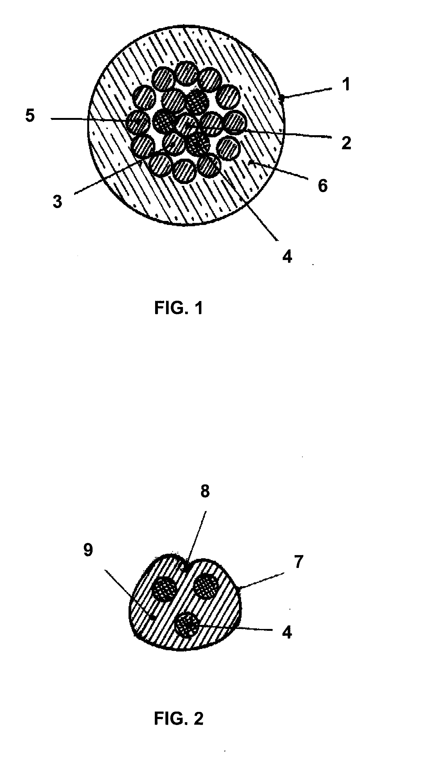
[0016]The invention will be described in more detail with reference to the exemplary embodiments shown in FIGS. 1 and 2.

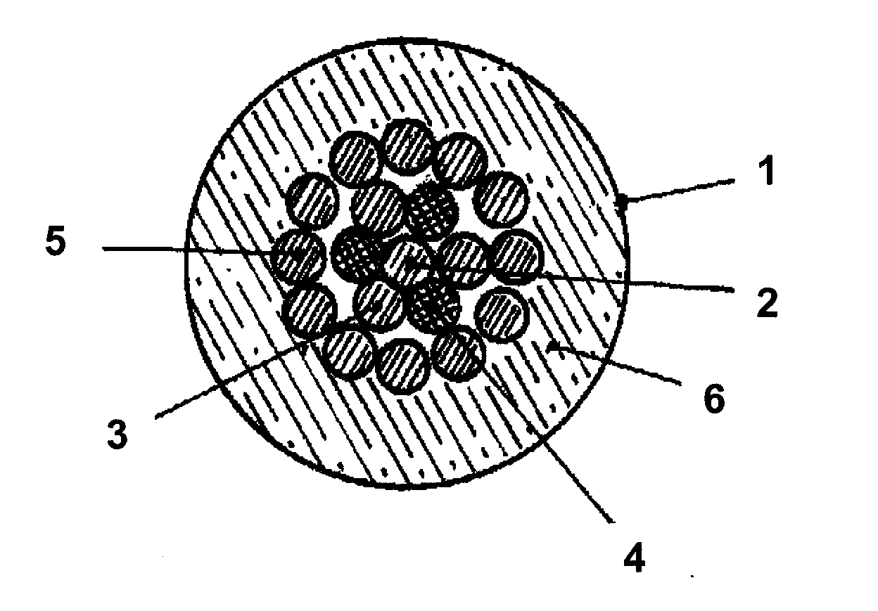
[0017]FIG. 1 shows a sectional view of an electrical cable 1, for example serving as a connecting line for a lambda sensor provided in a motor vehicle. The electrical conductor of this cable 1, according to the invention, comprises a central core wire 2 made of copper. Six individual wires are arranged in a first layer over this core wire 2, wherein these individual wires are configured as copper wires 3 and as steel wires 4, which alternate in succession in the circumferential direction. This results in a star-shaped arrangement of the tension-resistant, and thus somewhat rigid, steel wires 4, and therefore minimally impairs the flexibility of the extremely thin cable. A further twelve copper wires 5 are arranged in a second wire layer which, in the exemplary embodiment, form the outermost wire layer, to which an insulator 6 is finally applied. In the illustrated ...


PUM

PropertyMeasurementUnit
tensile forceaaaaaaaaaa
diameteraaaaaaaaaa
diameteraaaaaaaaaa

Abstract

A tension-resistant electrical conductor includes a central core wire and at least a first inner wire layer and a second outer wire layer arranged over the central core wire. The central core wire is made of copper or a copper alloy. The first inner wire layer includes, in the circumferential direction, an alternating sequence of copper wires and wires having higher tensile strength, arranged over the central core wire, and the second outer wire layer, and any further outer wire layer, is composed exclusively of copper wires.

Description

[0001]This application claims the benefit of German Patent Application No. 10 2009 060 419.7 filed on Dec. 22, 2009, which is hereby incorporated by reference.TECHNICAL FIELD[0002]The present invention relates to a tension-resistant electrical conductor, comprising a central core wire and at least two wire layers arranged over the core wire.BACKGROUND ART[0003]A conductor is described, for example, in EP 2096645 A1, where the desired tensile strength is achieved by a layer of steel wires, which is arranged over a core wire, which is made of copper. Such a conductor, having suitable insulation, is notably intended for use in wiring or sensor lines in the automotive industry, where small cross-sections, and consequently advantageous bending properties, as well as high flexibility and high tensile strength, are important.[0004]However, particularly in the field of sensor lines that serve, for example, as supply lines for so-called lambda sensors in the catalytic converters of motor veh...

Claims


Application Information

Patent Timeline
Patent Type & Authority Applications(United States)
IPC IPC(8): H01B3/30H01B5/00H02G15/02
CPCH01B7/04H01B7/0009
Inventor DLUGAS, WOLFGANG
Owner HEW KABEL
Why Eureka
Try Eureka