Novel carbon nanotubes synthesis continuous process using iron floating catalysts and MgO particles for CVD of methane in a fluidized bed reactor

a technology of carbon nanotubes and catalysts, applied in the field of new carbon nanotubes, can solve the problems of wasting catalysts, affecting the synthesis of carbon nanotubes, and severely limited cnts production efficiency in fixed-bed reactors, and achieve the effect of large surface area and catalyst was

Inactive Publication Date: 2011-06-23
KHODADADI ABBAS ALI +1
View PDF2 Cites 61 Cited by
  • Summary
  • Abstract
  • Description
  • Claims
  • Application Information

AI Technical Summary

Benefits of technology

[0008]The primary object of present invention is to provide a process for continuous production of carbon nanotubes (CNTs) by means of chemical vapor deposition (CVD) of methane over Fe / MgO catalyst produced by in-situ decomposition of ferrocene (floating catalyst) on fluidized MgO particles comprising steps of: forming Iron nanoparticles on MgO exterior surface by decomposition of ferrocene in the hot zone of the fluidized bed system. This way, in addition to provision of a large surface area for CNTs growth, the wasting of the catalyst in the internal porous structure of the catalyst, as in the common CVD catalysts, is prevented.
[0009]Still another object of the present invention is to provide a method for continuous production of carbon nanotubes by chemical vapor deposition of at least one carbon containing compound over a fluidized catalyst in a reactor, wherein said catalyst is synthesized inside said reactor by decomposition of at least one transition metal compound over at least one carrier.
[0017]In another aspect of the present invention, CNTs are grown on the fluidized Fe / MgO catalyst, rather than on the reactor walls. This facilitates the continuous CNTs withdrawal suitable for large scale production. Confining the ferrocene and MgO contact space by an annular tube leads to higher quality CNTs, due probably to smaller iron nanoparticles formed in the more efficient contact of ferrocene and MgO. Increasing the flow rate of ferrocene and decreasing the synthesis temperature results in higher quality CNTs. The highest IG / ID ratio of 10.2 is obtained at 900° C. with the annular tube in place. MWNTs of about 20 nm size as well as SWNTs of 1.0-1.2 nm diameter are formed in the fluidized bed system.
[0018]A continuous process is used for production of carbon nanotubes (CNTs) by catalytic chemical vapor deposition (CCVD) of methane on iron floating catalyst in-situ deposited on MgO in a fluidized bed reactor. In the hot zone of the reactor, sublimed ferrocene vapors were contacted with MgO powder fluidized by methane feed to produce Fe / MgO catalyst in-situ. An annular tube was used to enhance the ferrocene and MgO contacting efficiency. Multi-wall as well as single-wall CNTs were grown on the Fe / MgO catalyst while falling down the reactor. The CNTs were continuously collected at the bottom of the reactor, only when MgO powder was used. The annular tube enhanced the contacting efficiency and improved both the quality and quantity of CNTs.

Problems solved by technology

The efficiency of CNTs production in the fixed-bed reactor is severely limited by inhomogeneous gas-solid mixing along the catalyst bed, with the dense packing of the catalyst particle preventing both CNTs production and dissipation of by-products.
This situation is worsened by the growing nanotubes forming a mat that covers the catalyst bed.
Gas-solid fluidization is extremely difficult for ultrafine particles (including nanoparticles), since inter-particle forces are greater than the hydrocarbon.
This is because ultrafine particles adhere to each other tightly in all directions by van der Waals or other forces, which seriously limit their fluidization.

Method used


Image

  • Novel carbon nanotubes synthesis continuous process using iron floating catalysts and MgO particles for CVD of methane in a fluidized bed reactor
  • Novel carbon nanotubes synthesis continuous process using iron floating catalysts and MgO particles for CVD of methane in a fluidized bed reactor
  • Novel carbon nanotubes synthesis continuous process using iron floating catalysts and MgO particles for CVD of methane in a fluidized bed reactor

Examples


Embodiment Construction

Experimental Procedure

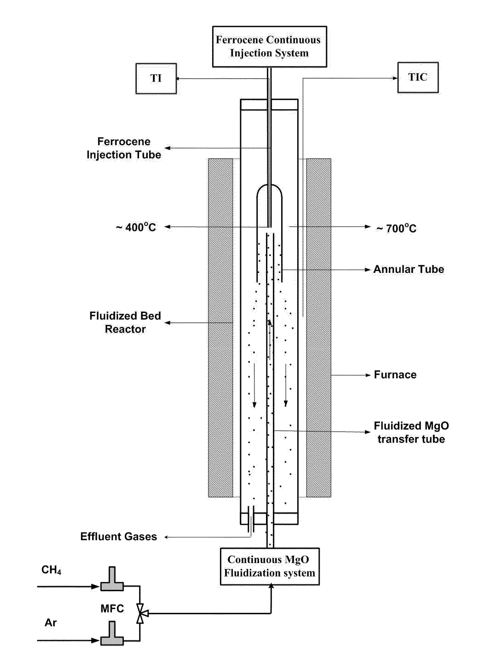
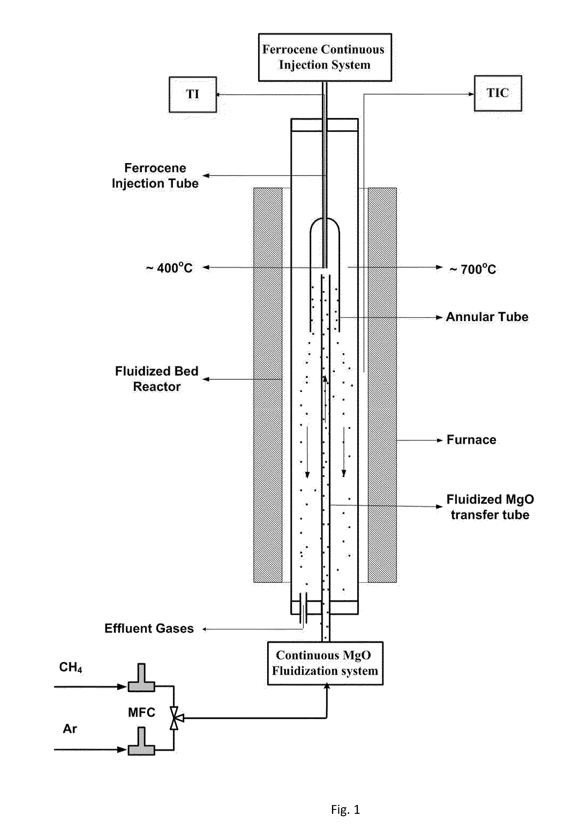
[0027]FIG. 1 shows the system used for synthesis of CNTs. The system has three main parts including ferrocene continuous injection and fluidized MgO introduction systems and the fluidized bed reactor.

[0028]The ferrocene injection system includes a tube packed with 60-100 mesh ferrocene particles, through which 60-120 sccm argon was flowing. The tube was placed in a constant and uniform temperature bath at 150° C. The ferrocene injection system is placed on top of the fluidized bed reactor and ferrocene is injected in the hot (˜700° C.) zone of the reactor, through an extended tube. An air cooling system was used to prevent overheating of the ferrocene in the tube to temperatures higher than 400° C. At temperatures higher than 460° C. ferrocene decomposition becomes significant. To enhance the contact of ferrocene and MgO in the reactor, a larger diameter (annular) tube covering both the ferrocene injection tube and the fluidized MgO introduction tube, was used....


PUM

PropertyMeasurementUnit
sizeaaaaaaaaaa
diametersaaaaaaaaaa
temperatureaaaaaaaaaa

Abstract

A novel continuous process is used for production of carbon nanotubes (CNTs) by catalytic chemical vapor deposition (CCVD) of methane on iron floating catalyst in-situ deposited on MgO in a fluidized bed reactor. In the hot zone of the reactor, sublimed ferrocene vapors were contacted with MgO powder fluidized by methane feed to produce Fe / MgO catalyst in-situ. An annular tube was used to enhance the ferrocene and MgO contacting efficiency. Multi-wall as well as single-wall CNTs were grown on the Fe / MgO catalyst while falling down the reactor. The CNTs were continuously collected at the bottom of the reactor, only when MgO powder was used. The annular tube enhanced the contacting efficiency and improved both the quality and quantity of CNTs. The SEM and TEM micrographs of the products reveal that the CNTs are mostly entangled bundles with diameters of about 20 nm. Raman spectra show that the CNTs have low amount of amorphous carbon with IG / ID ratios as high as 10.2 for synthesis at 900° C. The RBM Raman peaks indicate formation of single-walled carbon nanotubes (SWNTs) of 1.0-1.2 nm diameter.

Description

SPONSORSHIP STATEMENT[0001]The present invention is sponsored by Iran Nanotechnology Initiative Council, and Nanoscience and Nanotechnology Research center of University of Tehran (Iran).BACKGROUND OF THE INVENTION[0002]Carbon nanotubes (CNTs) have attracted considerable attention since their discovery due to their outstanding physical and chemical properties. Various synthesis methods have been developed for the production of CNTs, including electric arc discharge, laser vaporization, and catalytic chemical vapor deposition (CCVD). Many previous reports have shown the possibility of CNTs production on a large scale at a low cost.[0003]Different types of reactor configurations including fixed-bed micro-reactors or small fluidized-bed reactors with short contact times are employed for the CVD synthesis of CNTs. “Fixed bed”, “floating catalyst”, and “fluidized bed” method are most common processes for the CCVD growth of CNTs.[0004]The efficiency of CNTs production in the fixed-bed rea...

Claims


Application Information

Patent Timeline
Patent Type & Authority Applications(United States)
IPC IPC(8): D01F9/12C10G11/18
CPCB82Y30/00B82Y40/00C01B2202/36C01B31/024C01B2202/02C01B31/0233C01B32/162C01B32/164
Inventor KHODADADI, ABBAS ALIMORTAZAVI, YADOLLAH
Owner KHODADADI ABBAS ALI
Why Eureka
Try Eureka