
Miniature Thermoelectric Power Generator

a generator and miniature technology, applied in the manufacture/treatment of thermoelectric devices, thermoelectric devices with peltier/seeback effects, electrical apparatus, etc., can solve the problems of low thermal gradient in physically small structures, low thermal gradient in thin-film materials, and current batteries failing to meet this demand

Active Publication Date: 2011-06-30
UNIV OF FLORIDA RES FOUNDATION INC
View PDF12 Cites 11 Cited by
  • Summary
  • Abstract
  • Description
  • Claims
  • Application Information

AI Technical Summary

Benefits of technology

[0011]Embodiments of the present invention can incorporate thermal insulating polymers with the thermal conductivity, micromachinability, and process compatibility of silicon. This approach offers several advantages for higher performing and more integrable power generation systems. First, through careful design, the complementary thermal and mechanical properties of silicon and polymers can be exploited to enhance the performance of the generator system. For example, polymers can be used for thermal isolation, whereas silicon can be used for mechanical strength and thermally efficient heat fins Second, the silicon-based platform offers the potential for integration with other common complementary metal oxide semiconductor (CMOS) electronics or microelectromechanical systems (MEMS) for integrated sensing, actuation, data processing, control, and / or communications. Third, the use of silicon as a starting substrate (as opposed to a polymer) may permit the deposition / patterning of new semiconductor thin films that require high-temperature compatible, crystalline substrates.
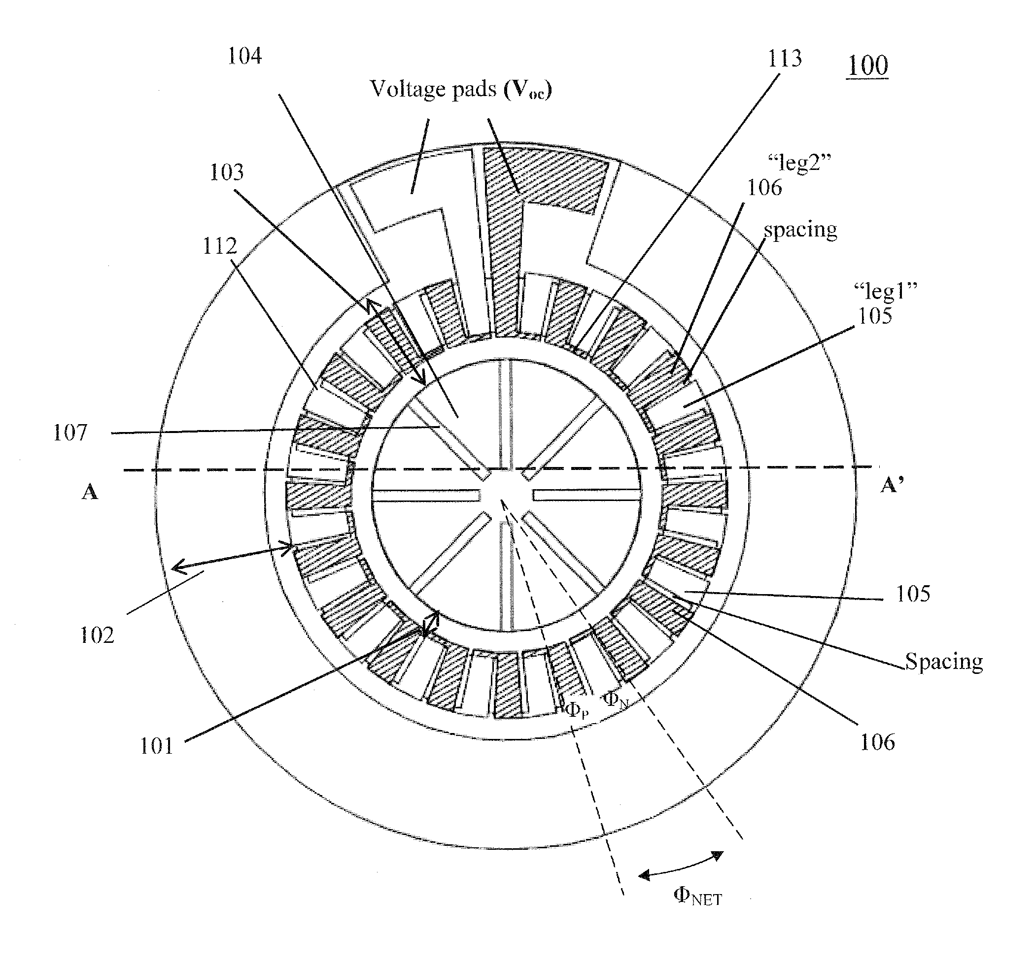
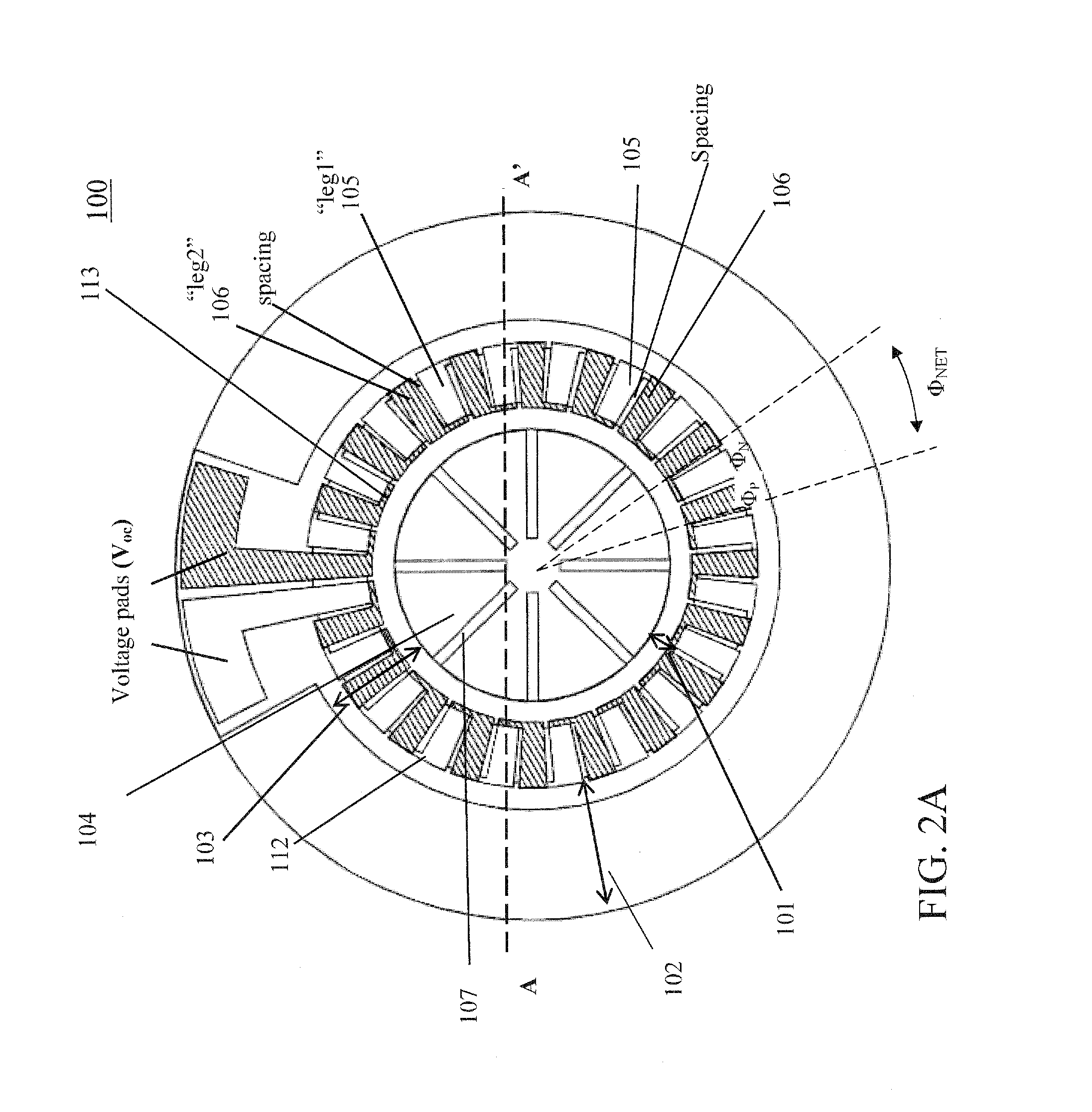
[0014]According to certain embodiments, a stack of silicon-micromachined chips can be connected to form a cylindrical heat exchanger that enables a large, uniform temperature difference across a radially-oriented thermopile. Each layer in the stack can comprise two they anally-isolated concentric silicon rings connected by a polyimide membrane that supports patterned thermoelectric thin films. The polyimide membrane can be formed by selectively etching away the supporting silicon, resulting in thermally-isolated inner and outer rings. In operation, hot gas flows through a finned central channel, and an external cross flow enhances heat transfer to ambient to keep the outer surfaces cool.

Problems solved by technology

For portable electronics, current batteries are failing to meet this demand.
Despite these advances, the integration of these thin-film materials into miniaturized generator platforms remains technologically challenging.
To achieve a functional TE module, one major challenge is the integration and reliable interconnection of numerous series-connected thermoelements, especially if two or more substrates are bonded together.
Another challenge is maintaining high thermal gradients in physically small structures.
Furthermore, present challenges to providing efficient thermoelectric power generation include thermal leakage and the temperature difference needed across hundreds of micrometers.

Method used


Image

  • Miniature Thermoelectric Power Generator
  • Miniature Thermoelectric Power Generator
  • Miniature Thermoelectric Power Generator

Examples


Embodiment Construction

[0024]Embodiments of the present invention relate to thermoelectric power generation. Thermoelectric generator modules and methods of fabricating the same are provided. The subject thermoelectric generator modules can be used as an in-line power source for self-powered sensors using hot gas lines in automotive, aerospace, industrial or military applications. Further applications can perform power generation using hot exhaust gasses from small heat engines or microcombustors.

[0025]When the terms “on” or “over” are used herein, when referring to layers, regions, patterns, or structures, it is understood that the layer, region, pattern or structure can be directly on another layer or structure, or intervening layers, regions, patterns, or structures may also be present. When the terms “under” or “below” are used herein, when referring to layers, regions, patterns, or structures, it is understood that the layer, region, pattern or structure can be directly under the other layer or struc...


PUM


Abstract

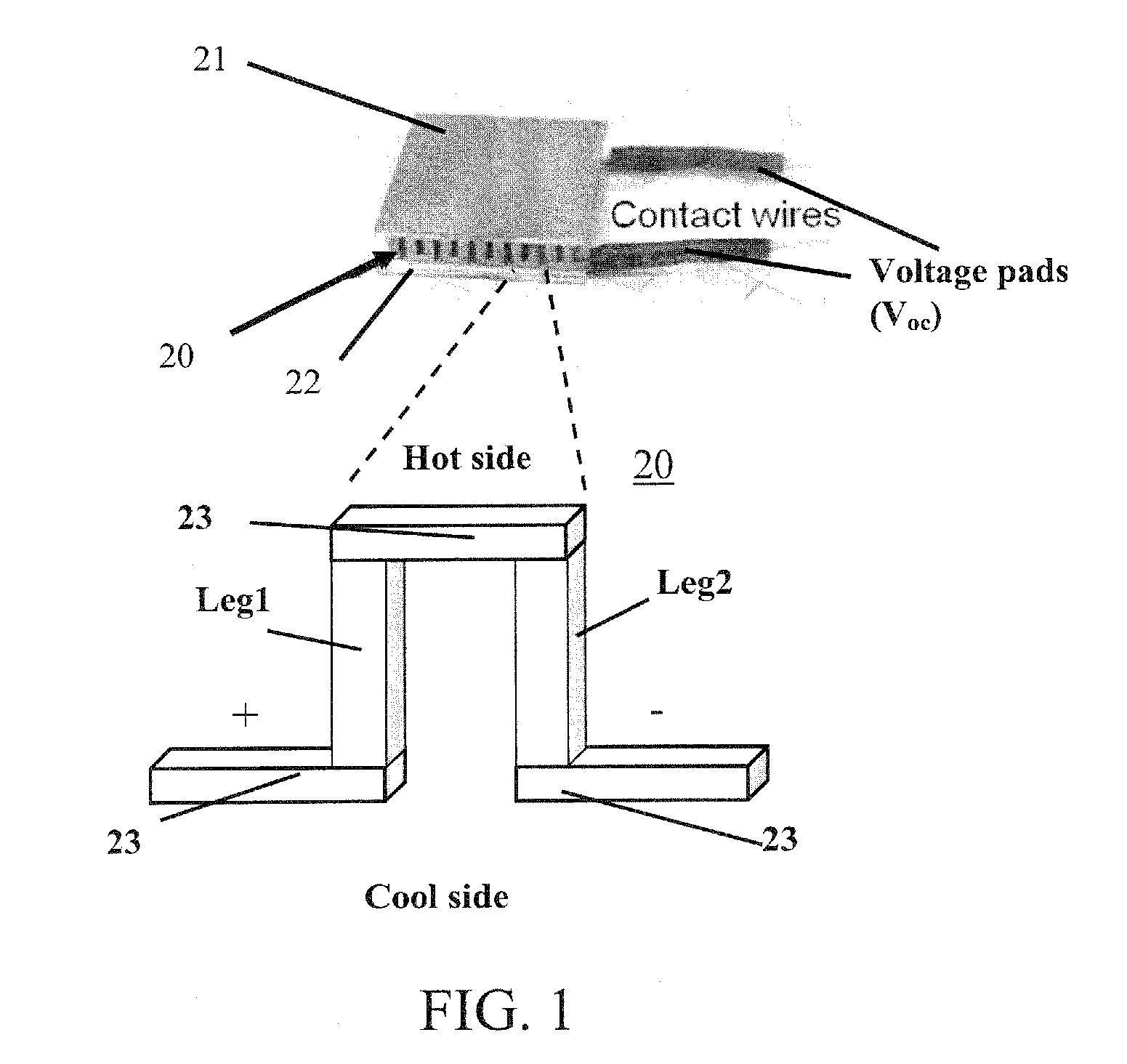
The subject invention pertains to thermoelectric power generation. According to certain embodiments, a stack of silicon-micromachined chips can be connected to form a cylindrical heat exchanger that enables a large, uniform temperature difference across a radially-oriented thermopile. Each layer in the stack can comprise two thermally-isolated concentric silicon rings connected by a polyimide membrane that supports patterned thermoelectric thin films. The polyimide membrane can be formed by selectively etching away the supporting silicon, resulting in thermally-isolated inner and outer rings. In operation, hot gas can flow through a finned central channel, and an external cross flow can enhance heat transfer to ambient to keep the outer surfaces cool. The resulting temperature gradient across the thermopile generates a voltage potential across the open ends due to the Seebeck effect. When connected to a load, current flows, and electrical power is supplied by the generated voltage potential caused by the temperature gradient.

Description

CROSS-REFERENCE TO RELATED APPLICATION[0001]The present application claims the benefit of U.S. Provisional Application Ser. No. 61 / 098,103, filed Sep. 18, 2008, which is hereby incorporated by reference in its entirety, including any figures, tables, or drawings.[0002]The subject invention was made with government support under US Army RDECOM ACQ CTR grant number W911NF-06-2-0004. The government has certain rights in the invention.BACKGROUND OF THE INVENTION[0003]As electronics grow smaller while expanding in functionality, the demand for higher energy density is increasing. For portable electronics, current batteries are failing to meet this demand. The ever-growing demand for wireless sensors and portable electronics has spurred research of new power sources to enhance system performance and extend lifespan.[0004]New technologies such as microscale heat engines, micro fuel cells, micro thermo-photovoltaic and micro-thermoelectric generation are being developed as possible high ene...

Claims


Application Information

Patent Timeline
Patent Type & Authority Applications(United States)
IPC IPC(8): H01L35/32H01L35/34
CPCH01L35/32H10N10/17
Inventor ARNOLD, DAVID PATRICKBONICHE, ISRAELMEYER, CHRISTOPHER DAVIDMASILAMANI, SIVARAMAN
Owner UNIV OF FLORIDA RES FOUNDATION INC
Learn More