
Anisotropic cte lsm for sofc cathode

a sofc and anisotropic technology, applied in the field of anisotropic cte lsm for sofc cathode, can solve the problems of large thermal mismatch stress in the sofc, undesirable to use an lsm with sr content, and the difference between the ctes of the lsm and the ysz materials, so as to reduce the failure rate of the sofc, minimize or significantly reduce the failure rate of the so

Inactive Publication Date: 2011-06-30
SAINT GOBAIN CERAMICS & PLASTICS INC
View PDF4 Cites 1 Cited by
  • Summary
  • Abstract
  • Description
  • Claims
  • Application Information

AI Technical Summary

Benefits of technology

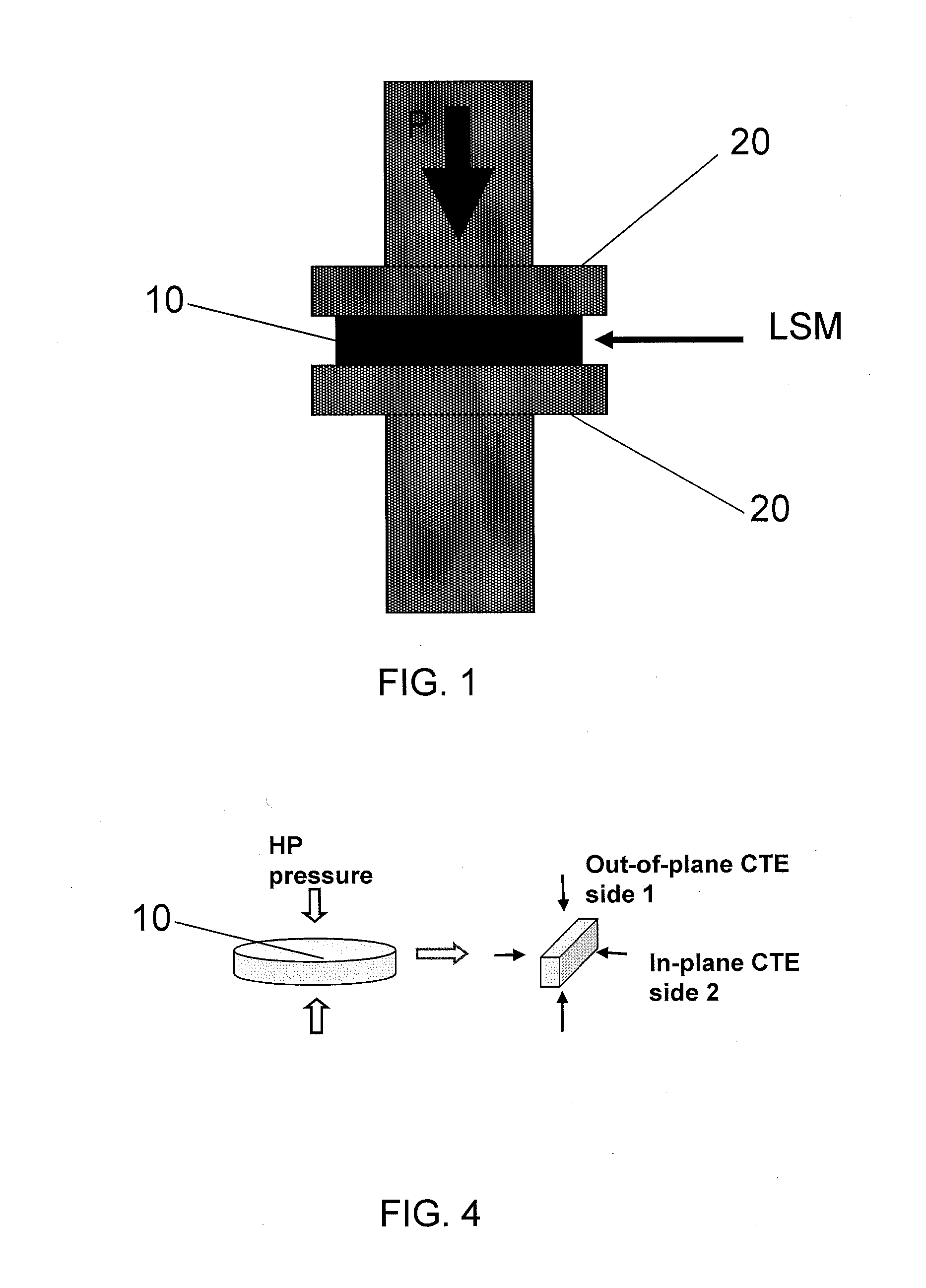
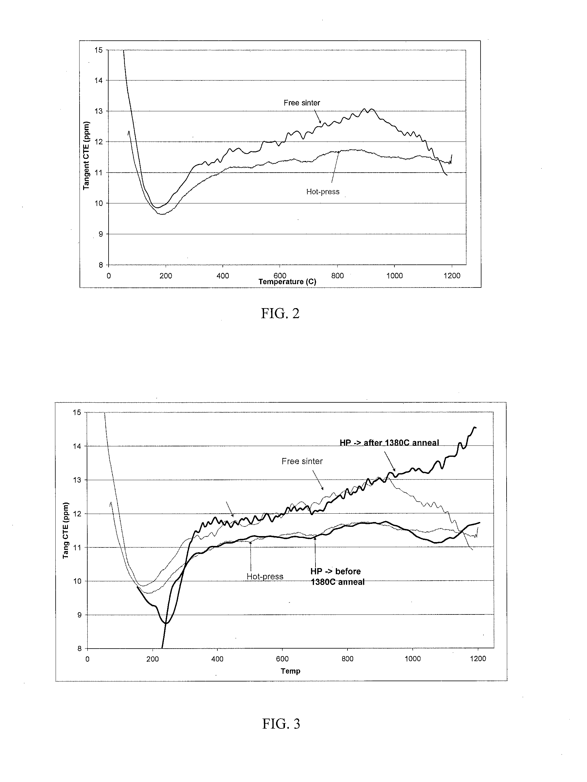
[0009]This invention has many advantages, including maintaining low thermal mismatch stresses in the cell and stack of a SOFC. As will be further described below, it has been found that compression of LSM during heat treatment lowers the CTE of the LSM, thereby minimizing or significantly reducing failure of SOFCs that employ LSM during use.

Problems solved by technology

Where there is sufficient mismatch of CTE among the layers, cooling, or any temperature change that is too rapid, can cause fracture and consequent failure of the SOFC.
The difference between the CTEs of the LSM and YSZ materials would generate a large thermal mismatch stress in the SOFC.
On the other hand, it is often undesirable to use an LSM with Sr content lower than 0.2, due to diminished electrochemical performance.

Method used


Image

  • Anisotropic cte lsm for sofc cathode
  • Anisotropic cte lsm for sofc cathode
  • Anisotropic cte lsm for sofc cathode

Examples


Embodiment Construction

[0019]The foregoing will be apparent from the following more particular description of example embodiments of the invention, as illustrated in the accompanying drawings in which like reference characters refer to the same parts throughout the different views. The drawings are not necessarily to scale, emphasis instead being placed upon illustrating embodiments of the present invention. The teachings of all patents, published applications and references cited herein are incorporated by reference in their entirety.

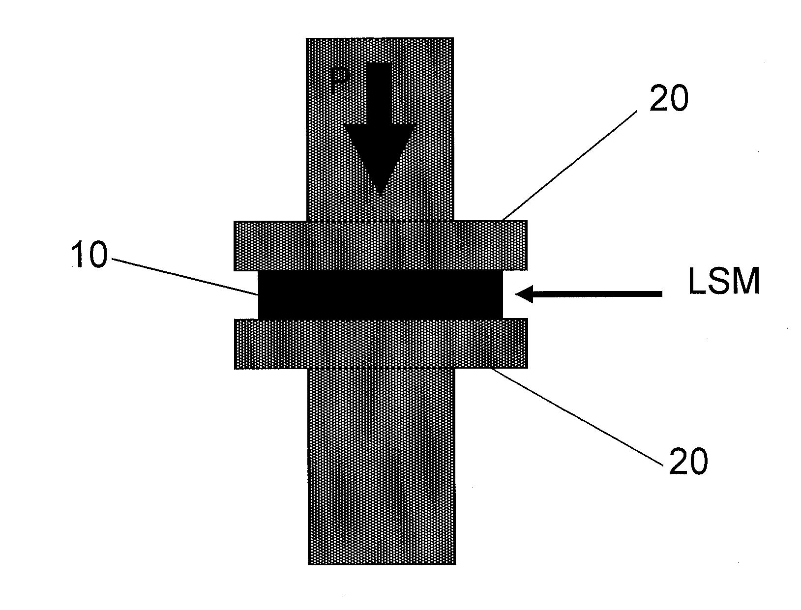
[0020]The invention generally is directed to a cathode having an anisotropic CTE and a method for forming the anisotropic CTE cathode of a solid oxide fuel cell. A SOFC stack can include the anisotropic CTE cathode, wherein the anisotropic CTE cathode can be made separately before stack fabrication or processed simultaneously with other layers of the SOFC stack. As used herein, the term solid oxide fuel cell includes a solid oxide electrolyser, that is, a solid oxide fuel ce...


PUM

PropertyMeasurementUnit
temperatureaaaaaaaaaa
thicknessaaaaaaaaaa

Abstract

An anisotropic coefficient of thermal expansion (CTE) cathode of a solid oxide fuel cell (SOFC) is formed by placing a layer of perovskite powder between two platens, and sintering the layer while applying pressure to the platens, thereby forming the anisotropic CTE cathode. The perovskite can be lanthanum strontium manganite (LSM).

Description

RELATED APPLICATION(S)[0001]This application claims the benefit of U.S. Provisional Application No. 61 / 335,085, filed on Dec. 31, 2009. The entire teachings of the above application are incorporated herein by reference.BACKGROUND OF THE INVENTION[0002]A fuel cell is a device that generates electricity by a chemical reaction. Typically, in a fuel cell, an oxygen gas, such as O2, is reduced to oxygen ions (O2−) at the cathode, and a fuel gas, such as H2, is oxidized with the oxygen ions to form water at the anode. Among various types of fuel cells, solid oxide fuel cells (SOFCs) use hard ceramic compounds of metal oxides (e.g., calcium or zirconium oxides) to form components of the fuel cell, such as, for example, the anode, cathode, electrolyte, and interconnect. Fuel cells are generally designed as stacks, whereby subassemblies, each including a cathode, an anode and a solid electrolyte between the cathode and the anode, are assembled in series by locating an electrical interconnect...

Claims


Application Information

Patent Timeline
Patent Type & Authority Applications(United States)
IPC IPC(8): C01F17/00C04B35/36
CPCC04B35/016C04B35/645C04B2235/3206C04B2235/3208C04B2235/3227C04B2235/3229H01M4/8875C04B2235/661C04B2235/662C04B2235/668C04B2235/9607H01M4/88H01M4/9025C04B2235/656Y02E60/50H01M8/02H01M8/12
Inventor MAHONEY, F. MICHAELNARENDAR, YESHWANTHHUANG, HANSONG
Owner SAINT GOBAIN CERAMICS & PLASTICS INC
Learn More