
Cryo Activated Drug Delivery and Cutting Balloons

a technology of activated drugs and cutting balloons, which is applied in the field of cryo activated drug delivery and cutting balloons, can solve the problems of high loss, dosage variation, and difficult to effectively deliver effective doses when the balloon is inflated, and achieves the effect of facilitating placement and lesion crossing, relative softness of the blade, and facilitating the placement of the lesion

Inactive Publication Date: 2011-06-30
BOSTON SCI SCIMED INC
View PDF99 Cites 53 Cited by
  • Summary
  • Abstract
  • Description
  • Claims
  • Application Information

AI Technical Summary

Benefits of technology

[0018]In some embodiments the auxiliary functional structure comprises a blade or member that stiffens portions of the balloon when the member is in its glassy state. For delivery, the relative softness of the blade or stiffener at body temperature facilitates placement and lesion crossing. When inflated at cryotreatment temperature, the blade, stiffener, or force concentrator becomes sufficiently rigid to operate effectively for its designated function. Upon rewarming to body temperature the auxiliary functional structure again becomes more flexible facilitating removal.

Problems solved by technology

However the delivery technique still suffers from a fundamental conflict between the contradictory needs to deliver an effective dose at the treatment site and to keep the drug adhering to the balloon as it is being manipulated to that site.
Techniques to improve drug adhesion, such as formulation with polymers or other excipients or application of protective layers, make it more difficult to effectively deliver an effective dose when the balloon is inflated.
Conversely if the drug is applied to the balloon unformulated, or is formulated with a highly soluble excipient, for instance contrast agents such as iopamide, or sugars such as sucrose or mannitol, undesirably high losses and dosage variation can result.
However the commercial balloons do not yet provide for delivery of predictable amounts of the drug to the tissue at the delivery site nor do they provide for a predictable therapeutic drug tissue level over an extended time period.
Nor do they address differences in downstream drug loss due to tracking the device through different anatomies.
These devices have their own difficulties in design because of the added stiffness and the necessary protection for the blades.
Balloons with stiffeners or force concentrators that provide for higher pressure inflation or focus the balloon pressure at particular locations also can present problems in delivery because of the added stiffness of the added structures.

Method used


Image

  • Cryo Activated Drug Delivery and Cutting Balloons
  • Cryo Activated Drug Delivery and Cutting Balloons
  • Cryo Activated Drug Delivery and Cutting Balloons

Examples


Embodiment Construction

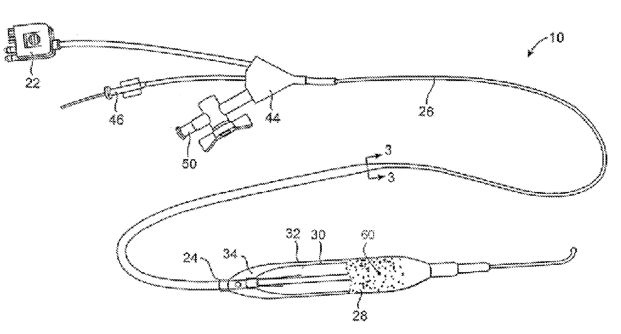
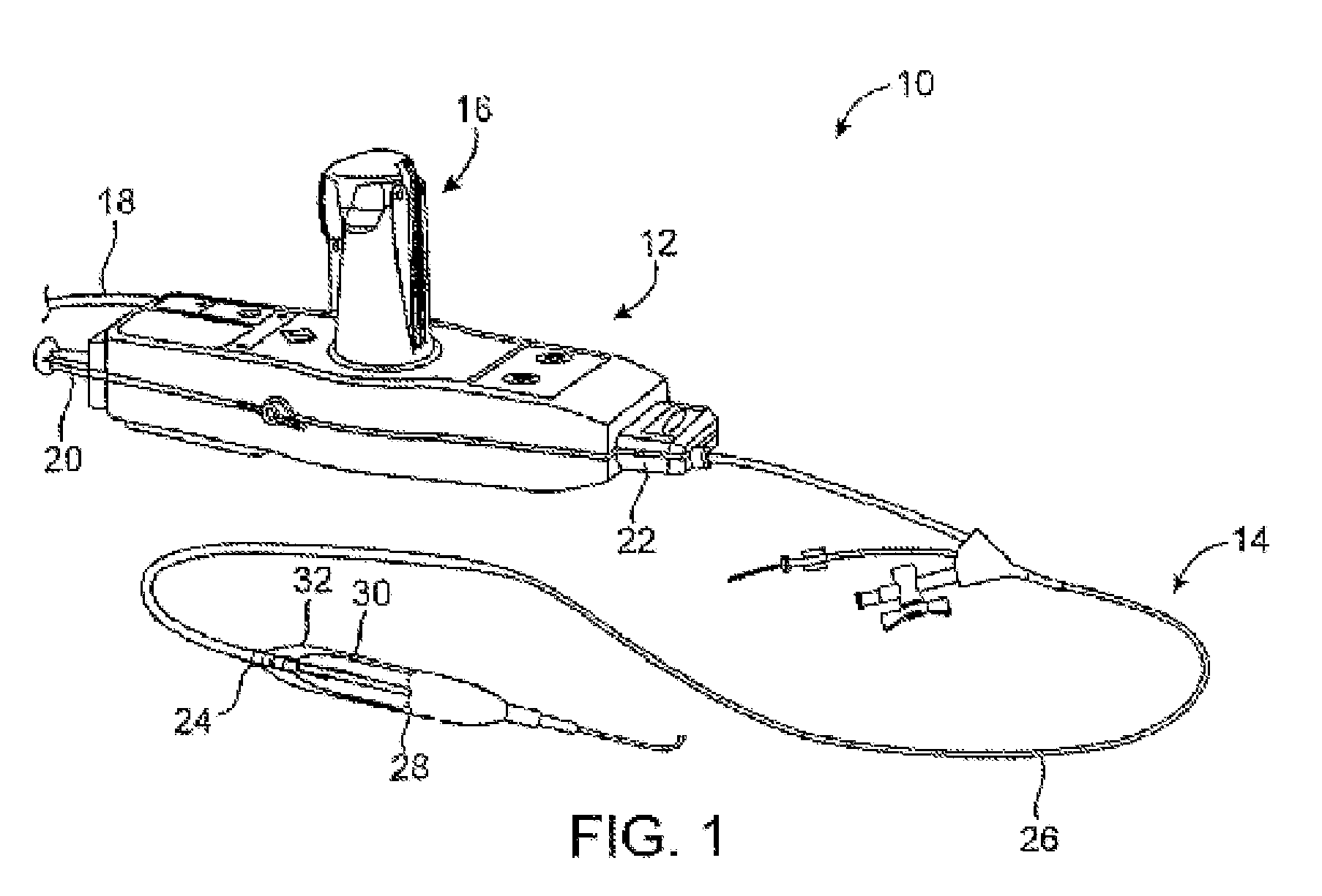
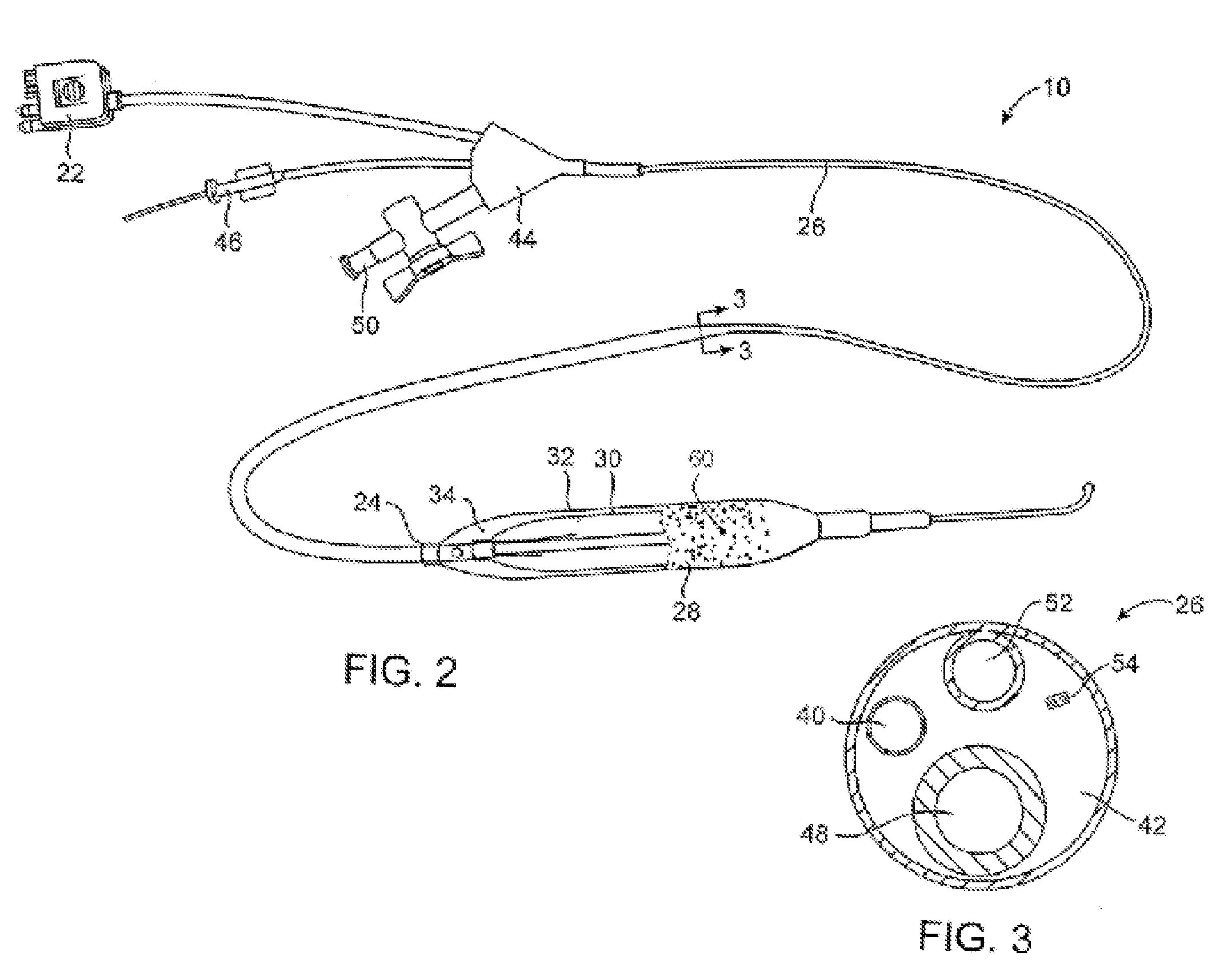
[0028]In some embodiments the inventive device uses a cryotherapy balloon combined with cutting balloon technology and / or with drug delivery balloon technology. This provides a combination of short term and long term treatments that are suited to treat specific stenoses with therapies that reduce restenosis, and at the same time allows for improvement in the delivery of these auxiliary functional technologies.

[0029]Non-limiting examples of cryotherapy systems are described in the following patents assigned to CryoVascular Systems, Inc.,[0030]U.S. Pat. No. 7,081,112, titled “Cryogenically enhanced intravascular interventions;”[0031]U.S. Pat. No. 7,060,062, titled “Controllable pressure cryogenic balloon treatment system and method;”[0032]U.S. Pat. No. 6,972,015, titled “Cryosurgical fluid supply;”[0033]U.S. Pat. No. 6,908,462, titled “Apparatus and method for cryogenic inhibition of hyperplasia;”[0034]U.S. Pat. No. 6,811,550, titled “Safety cryotherapy catheter;”[0035]U.S. Pat. No. 6...


PUM


Abstract

Physical property changes in materials between body temperature and a cryotreatment temperature are used to benefit auxiliary functional structures on a cryotherapy device. The auxiliary functional structures may be drug delivery coatings, cutting balloon blades, balloon stiffeners or force concentrators.

Description

CROSS-REFERENCE TO RELATED APPLICATIONS[0001]This application claims the benefit of Application No. 61 / 291,616, filed Dec. 31, 2009, the entire contents of which is hereby incorporated by reference.BACKGROUND OF THE INVENTION[0002]Percutaneous intravascular procedures have been developed for treating atherosclerotic disease in a patient's vasculature. The most successful of these treatments is percutaneous transluminal angioplasty (PTA). PTA employs a catheter having an expansible distal end, usually in the form of an inflatable balloon, to dilate a stenotic region in the vasculature to restore adequate blood flow beyond the stenosis. Other procedures for opening stenotic regions include directional atherectomy, rotational atherectomy, laser angioplasty, stents and the like.[0003]Sometimes following an initially successful angioplasty or other primary treatment restenosis occurs within weeks or months of the primary procedure. Restenosis results at least in part from smooth muscle c...

Claims


Application Information

Patent Timeline
IPC IPC(8): A61L29/16A61B18/02A61M25/10A61B17/32A61F2/958
CPCA61B17/320725A61B18/02A61B2017/00867A61B2017/22061A61B2017/22082A61M2025/109A61B2018/0212A61M25/104A61M2025/1013A61M2025/105A61M2025/1086A61B2018/0022
Inventor SUTERMEISTER, DEREKANDERSON, JAMES
Owner BOSTON SCI SCIMED INC
Learn More