Multibeam System

a multi-beam system and charger technology, applied in the field of multi-beam systems of chargers, can solve the problems of high-precision milling or sample removal that often requires some tradeoffs, and the processing rate of liquid metal ion sources is limited, and achieves the effect of great precision

Inactive Publication Date: 2011-07-07
UTLAUT MARK +6
View PDF40 Cites 64 Cited by
  • Summary
  • Abstract
  • Description
  • Claims
  • Application Information

AI Technical Summary

Problems solved by technology

Unfortunately, high-precision milling or sample removal often requires some tradeoffs.
The processing rate of the liquid metal ion source is limited by the current in the beam.
As the current is increased, it is harder to focus the beam into a small spot.
Lower beam currents allow higher resolution, but result in lower erosion rates and hence longer processing times in production applications and in laboratories.
Such systems, however, typically provide a reactive plasma over the entire surface of a wafer and are not used to locally etch or deposit fine features.
The gas ion beam described in Takahashi is used to produce a finished surface on the sample, but has insufficient resolution to extract a sample or to mill / deposit fine features.

Method used


Image

  • Multibeam System
  • Multibeam System
  • Multibeam System

Examples


Embodiment Construction

[0019]Preferred embodiments of the present invention combine a high resolution LMIS FIB with an additional beam for rapid material removal or processing, for example a plasma beam or a femtosecond laser, in order to provide an extended range of milling applications within the same system. In some embodiments, one or more additional beams can be used, including for example an electron beam for nondestructive imaging of the sample.

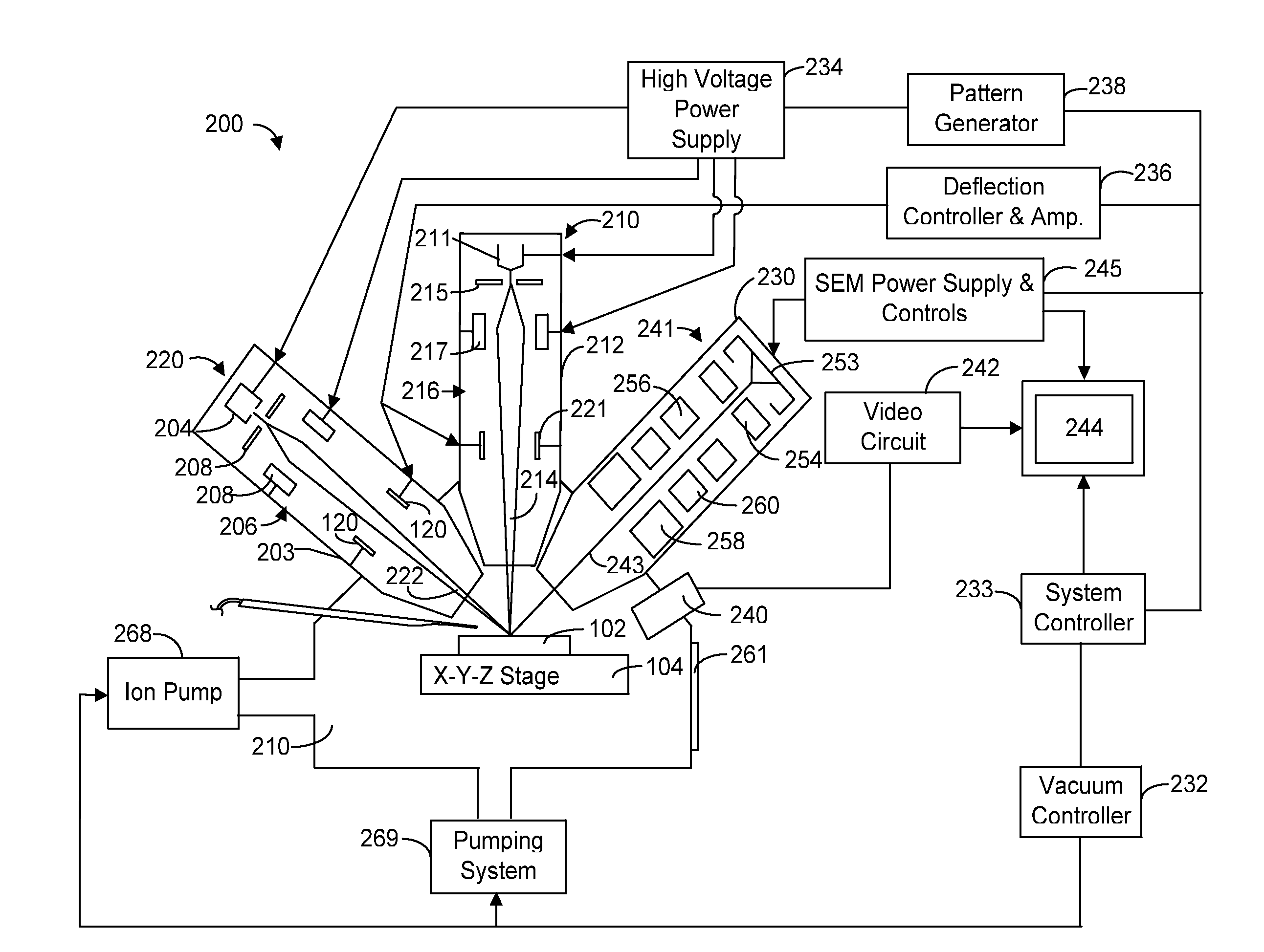
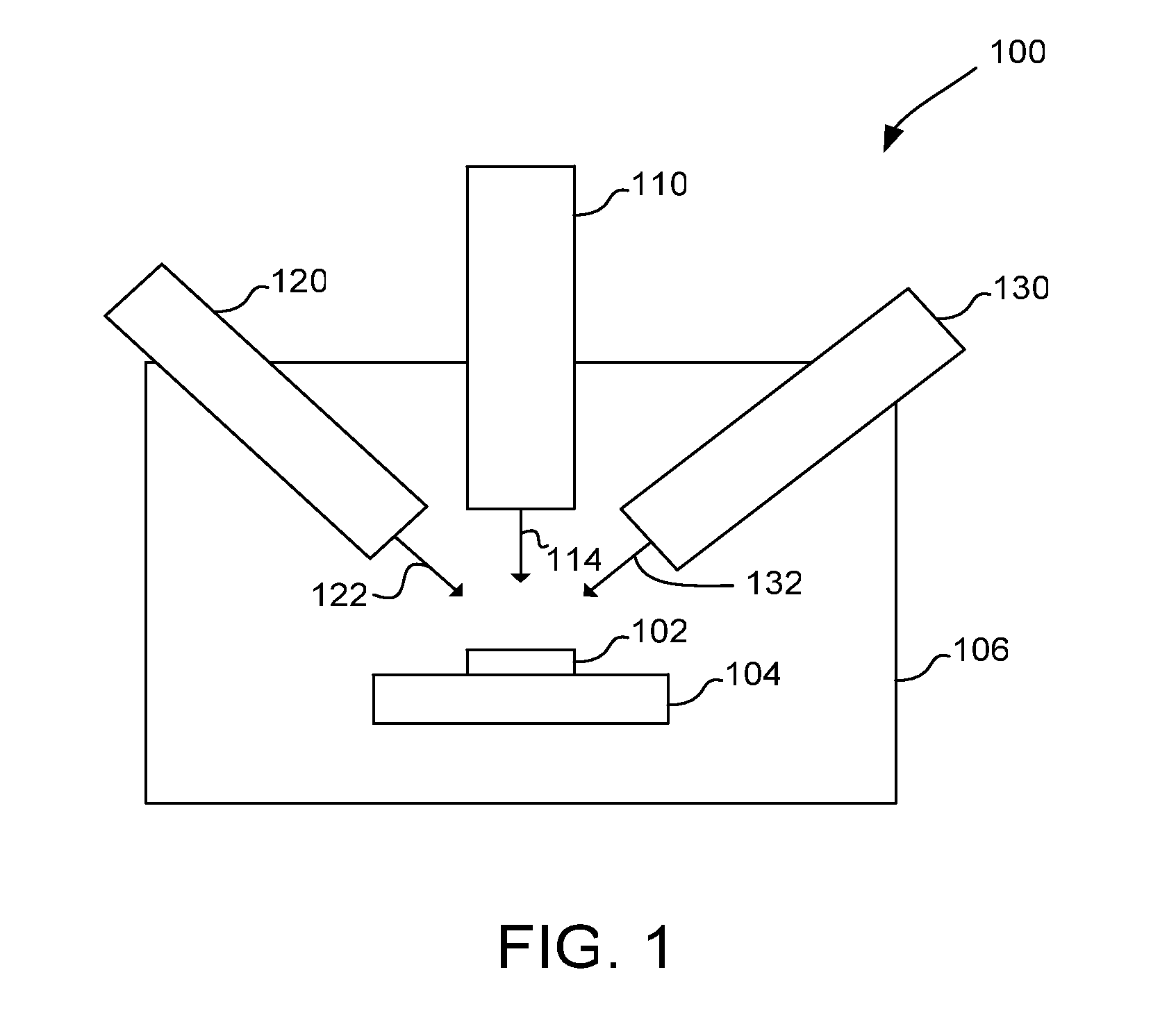
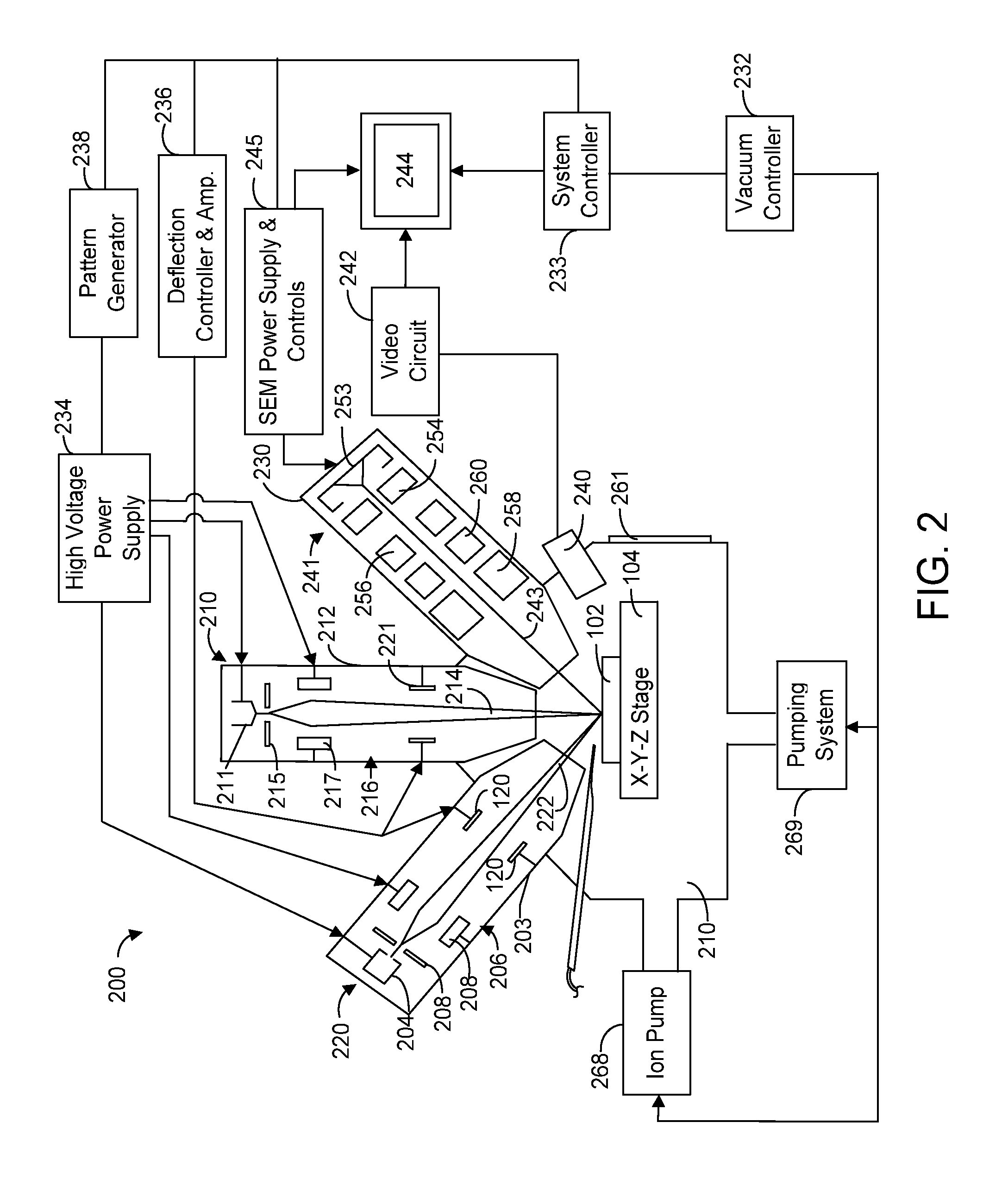
[0020]FIG. 1 shows a preferred embodiment of a multibeam system 100 of the invention in which a charged particle beam and two additional beams can be directed at a target within a single vacuum chamber. A first beam column produces a beam for rapid processing, a second beam column for producing a beam for more precise processing, and a third beam column for producing a beam useful for forming an image of the sample while producing little or no changes in the sample.

[0021]Multibeam system 100 includes a charged particle beam column 110 capable of generating a...


PUM

PropertyMeasurementUnit
diameteraaaaaaaaaa
diameteraaaaaaaaaa
angleaaaaaaaaaa

Abstract

A multibeam system in which a charged particle beam and one or more additional beams can be directed to the target within a single vacuum chamber. A first beam colunm preferably produces a beam for rapid processing, and a second beam column produces a beam for more precise processing. A third beam column can be used to produce a beam useful for forming an image of the sample while producing little or no change in the sample.

Description

TECHNICAL FIELD OF THE INVENTION[0001]The present invention relates to charged-particle beam multibeam systems.BACKGROUND AND SUMMARY OF THE INVENTION[0002]Charged particle beam systems are used in a variety of applications, including the manufacturing, repair, and inspection of miniature devices, such as integrated circuits, magnetic recording heads, and photolithography masks. Dual beam systems often include a scanning electron microscope (SEM) that can provide a high-resolution image with minimal damage to the target, and an ion beam system, such as a focused or shaped beam system, that can be used to alter workpieces and to form images. Ion beam systems using gallium liquid metal ion sources (LMIS) are widely used in manufacturing operations because of their ability to image, mill, deposit and analyze with great precision. Ion columns in FIB systems using gallium liquid metal ion sources (LMIS), for example, can provide five to seven nanometers of lateral resolution.[0003]Dual b...

Claims


Application Information

Patent Timeline
Patent Type & Authority Applications(United States)
IPC IPC(8): C23F1/08C23F1/00
CPCG03F1/84H01J37/228H01J37/3007H01L21/2633H01L21/0273H01L21/0274H01L21/0279H01J37/3056
Inventor UTLAUT, MARKSMITH, NOELTESCH, PAUL P.MILLER, TOMNARUM, DAVID H.TUGGLE, DAVIDSCIPIONI, LAWRENCE
Owner UTLAUT MARK
Why Eureka
Try Eureka