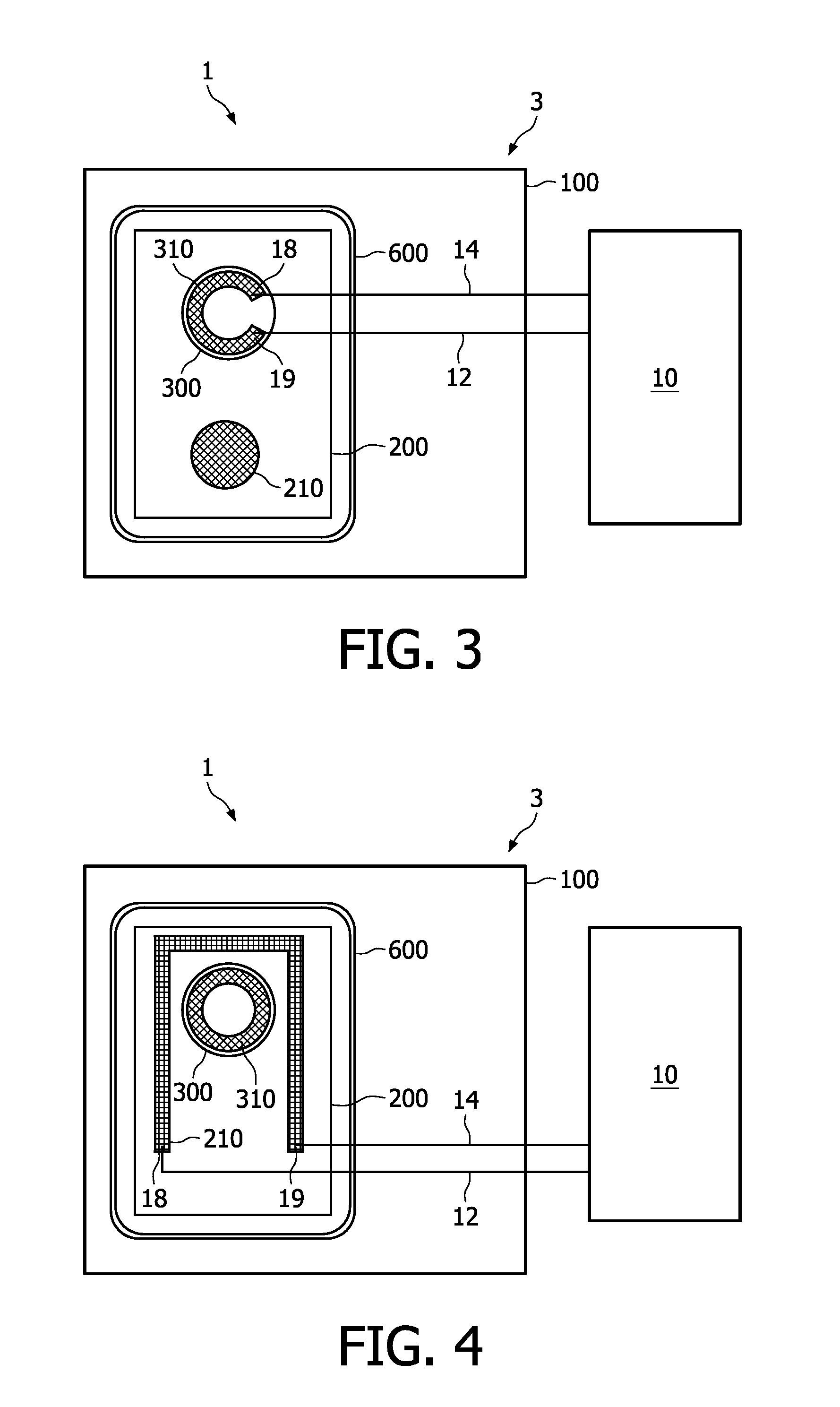
[0021]According to a further embodiment, at least one of the electric contacts for electrically connecting the semiconductor
laser diode and the integrated photodiode has two terminal points or electrodes connecting to the circuitry for stabilizing or setting the laser
wavelength. In this case, the heating current controlled by the circuitry flows laterally through the
electric contact between the two terminal points. A further possibility is to partially conduct the heating current through the substrate or layer underneath the respective
electric contact. Accordingly, instead of using an
electric contact with two terminal points, the electric contact may also be split into two laterally separated contacts. The heating current or
voltage is thus fed between two separated electric contacts on a common surface, at least one of the electric contacts contacting the semiconductor laser
diode or the integrated photodiode. To increase the resistance of this type of
heating element, the separate electric contacts can be produced from different materials. Specifically, while one contact may be a standard alloyed contact, the other one may be a simple
metal contact causing additional high losses and thereby increasing the overall resistance comprising the
contact resistance and
sheet resistance.
[0026]Alternatively or additionally, the light output as measured by the integrated photodiode can be used as an input parameter for the
feedback control circuitry. According to an advantageous refinement of the invention, the input of the
feedback control circuitry is thus connected to the electric contacts of the integrated photodiode, and the light output as measured by the integrated photodiode is fed as an input parameter to the
feedback control circuitry which sets the heating current or
voltage in dependence upon the light output. Although this parameter is somewhat sensitive to feedback, particularly under lasing conditions, this embodiment also has a very simple design as no additional temperature sensor is required. Furthermore, as already mentioned above, the temperature dependence of the
laser intensity is very strong, which allows a
highly sensitive temperature measurement.
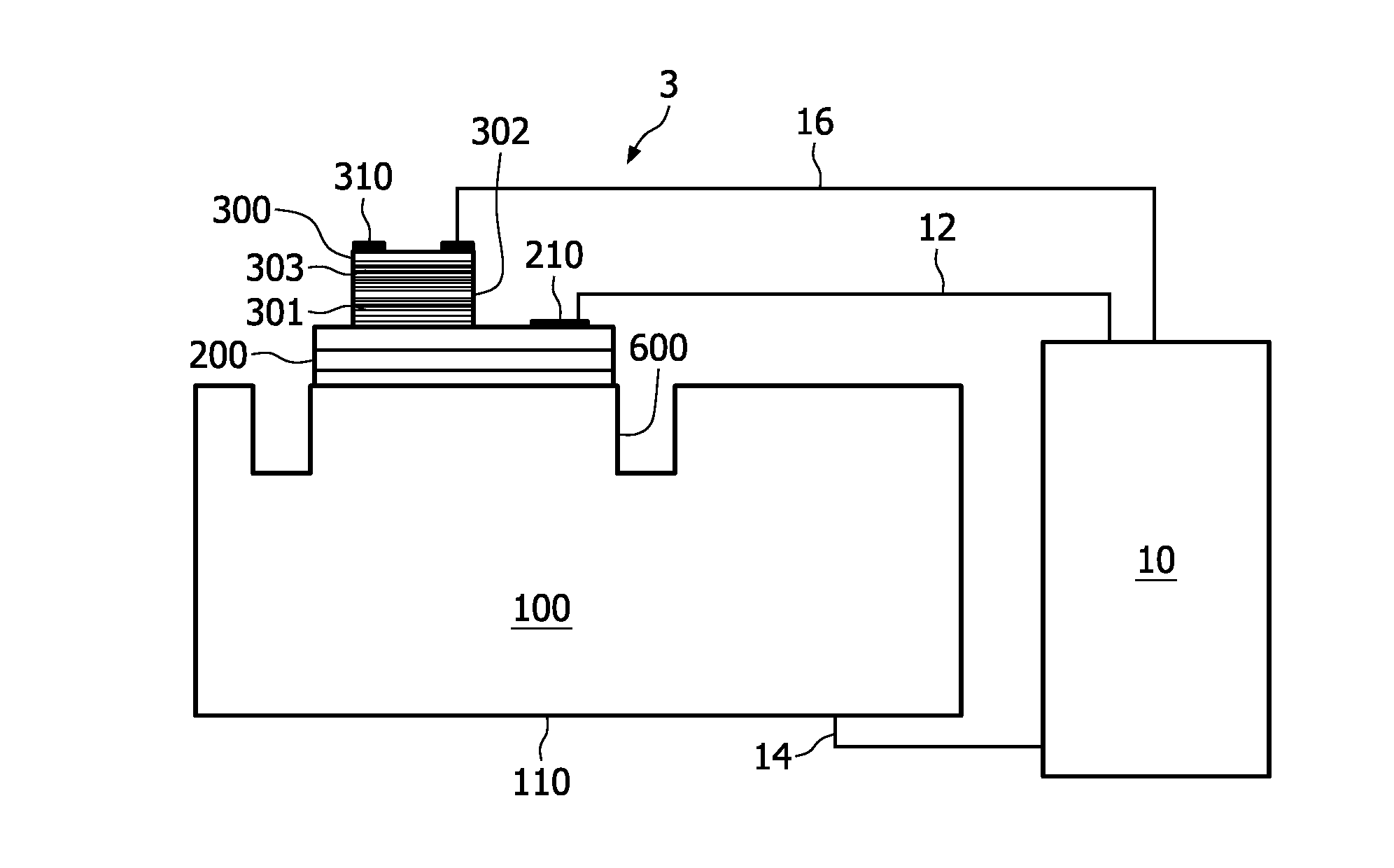
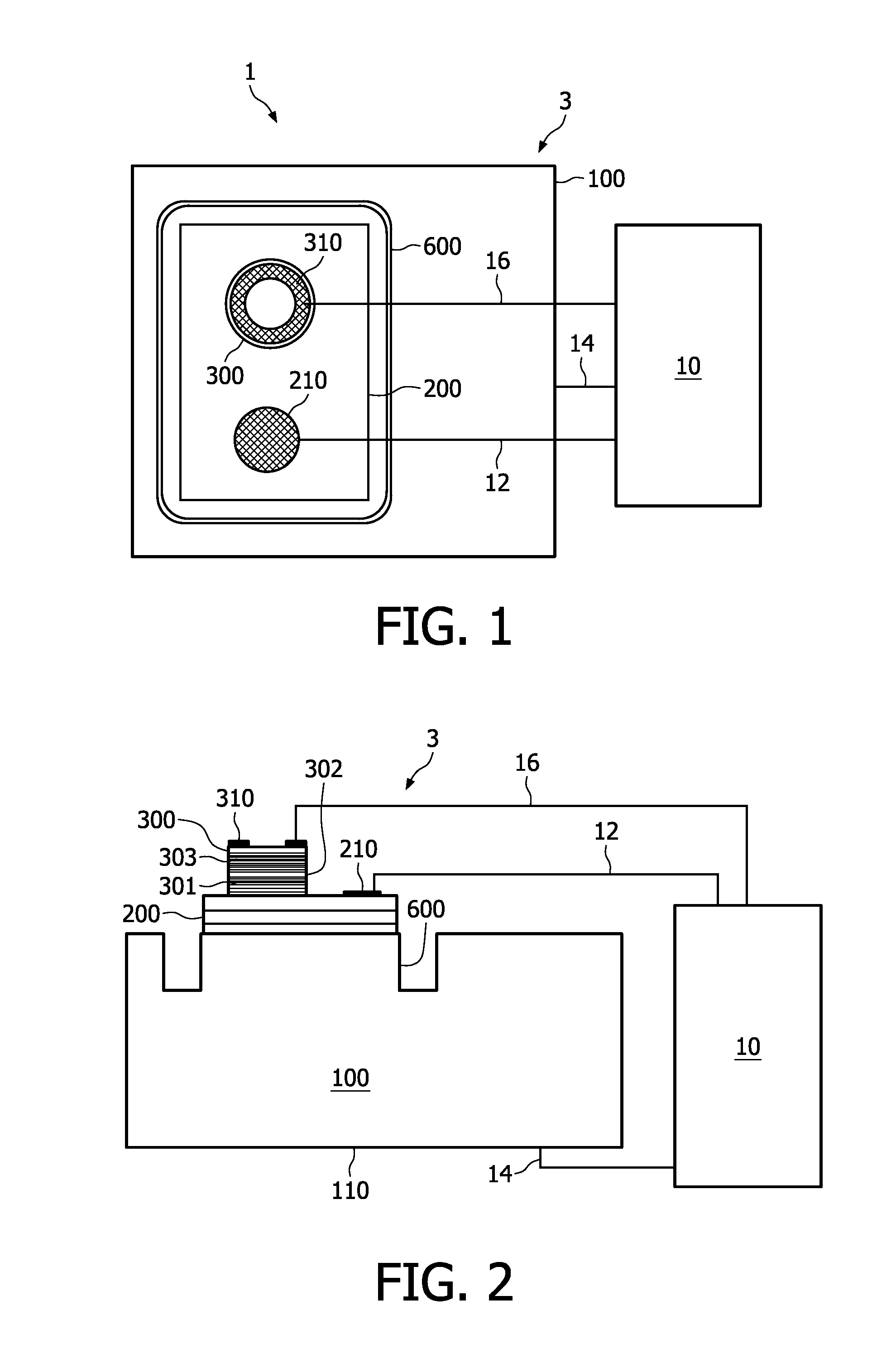
[0028]To reduce the power needed to heat the laser diode to the desired temperature and simultaneously render the
feedback loop faster, it is also advantageous to employ a semiconductor laser diode formed as a mesa structure on a substrate, which mesa structure is at least partly surrounded by a trench in the substrate. The trench reduces the heat dissipation laterally along the substrate.
[0030]Up to now, laser diodes have generally been cooled so as to optimize their lifetime and efficiency. However, cooling, in particular
active cooling requires additional components. If the laser diode is cooled passively, the ambient temperature limits the
working temperature. However, depending on the application, the ambient temperature can fluctuate to a great extent. Typical applications in an environment of fluctuating ambient temperatures are sensors for vehicles, in particular automotive, nautical or
aviation sensors. As a general idea of the invention,
active cooling of laser sensors can be avoided if the laser diode is operated at the high temperature end of applications in the typical range of ambient temperatures. For this purpose, use of a
heating element so as to significantly reduce the range of temperatures is proposed, so that the laser diode such as a VIP is always operated at temperatures well above the
lower limit of the ambient temperature range that is typical of the application. However, for temperature ranges up to temperatures at which a negative
impact on the laser diode lifetime can be expected, it is a preferred possibility to operate the VCSEL at medium temperatures, which still reduces the total span of occurring temperatures by a factor of, e.g., at least 2. In this case, time intervals in which the laser diode is operated at e.g. >100° C. can be shortened while still reducing the temperature range of operation. It is therefore generally preferred to set the
operating temperature below the temperature range which is detrimental to the lifetime of the laser diode.
[0036]The temperature range in nautical and
aviation applications is generally similar. Depending on the application, the temperature of the laser diode may also be set to be higher or lower. However, the temperature which is stabilized by the feedback control circuitry is preferably below 100° C., more preferably below 80° C. so as to ensure stable operation and a long lifetime.

