High torque limited angle compact and lightweight actuator

a compact and lightweight actuator technology, applied in the field of robots, can solve the problems of reducing mechanical efficiency, and increasing friction and mechanical play, and achieving the effect of torque/weight and torque/size ratio

Inactive Publication Date: 2011-07-21
SCUOLA SUPERIORE DI STUDI UNIVERSITARI E DI PERFEZIONAMENTO SANTANNA
View PDF2 Cites 14 Cited by
  • Summary
  • Abstract
  • Description
  • Claims
  • Application Information

AI Technical Summary

Benefits of technology

[0014]It is a feature of the present invention to provide an actuator with torque / weight and torque / size ratios that are improved with respect to the prior art.
[0015]It is also a feature of the present invention to provide an actuator that presents a high mechanical efficiency and low friction.
[0034]Preferably, said reduction unit is a ball nut / screw device, which is suitable to ensure less rolling resistance between the screw and the nut, as well as to ensure a high mechanical efficiency and minimum play, up to zero, in the two movement directions of said movable element.
[0035]Advantageously, said rotational motor is an electric hollow torque motor that has a high torque / weight and torque / size ratios and is such that it allows an easy integration with said nut / screw reduction device is achieved.

Problems solved by technology

The use of a reduction unit in the implementation of actuators allows to augment the torque / weight and torque / size ratios, but with the disadvantage of reducing mechanical efficiency and increasing friction and mechanical play.
In fact, the weight of the reduction unit is remarkably more limited, and a mechanical efficiency that is relatively higher and a friction and backlash sensibly lower or even near to zero are obtained.
An additional problem that affects this technique with respect to the other (for example epicyclic reduction gears), is that the movement of the screw has to be converted from linear to rotational.
This device, however has the drawback of a relatively high longitudinal encumbrance that is as much greater as the translation stroke of the screw and the radius of the pulleys increase.

Method used


Image

  • High torque limited angle compact and lightweight actuator
  • High torque limited angle compact and lightweight actuator
  • High torque limited angle compact and lightweight actuator

Examples


Embodiment Construction

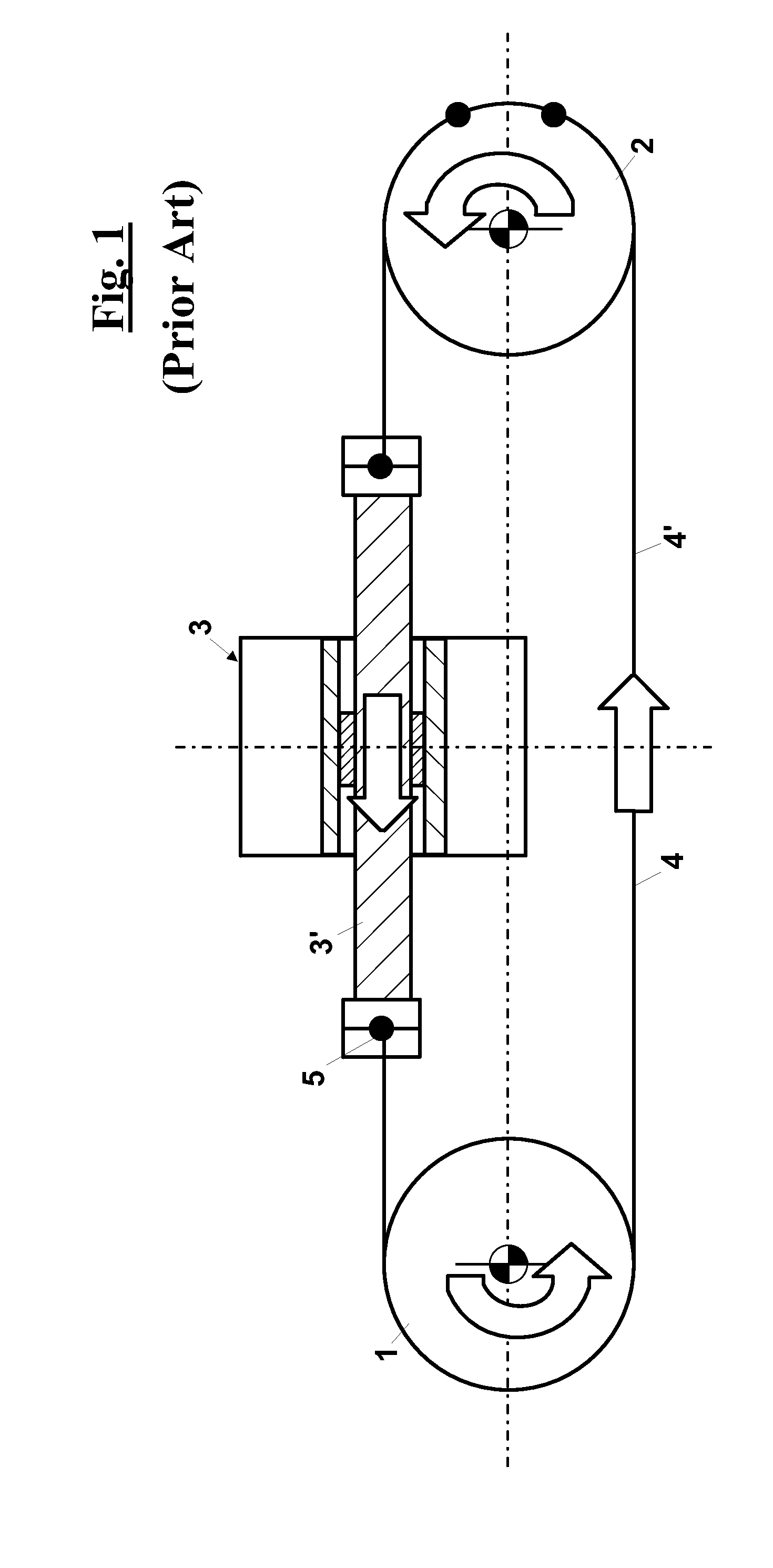
[0063]With reference to FIG. 1, an actuator is shown according to the prior art, which comprises mainly a first pulley 1 and a second 2 pulley, a motor 3, a ball nut / screw device 5 and two branches of tendons 4 and 4′ that allow to transfer the movement in both rotation directions of the pulleys. In particular, the axis of pulley 2, which is a driven pulley, is coincident to the output axis of the actuator, whereas the pulley 1, which is an idle pulley, is arranged on the rear part of a motor / reduction gear. The first portion, or branch, of tendon 4 is connected to one end of the ball nut / screw device 5, as well as it is directly connected to driven pulley 2, whereas the second portion, or branch, of tendon 4′ is wound on idle pulley 1 and it is connected to the second end of the ball nut / screw device and, also, to driven pulley 2.

[0064]This way, driven pulley 2 is caused to rotate in a clockwise, or counterclockwise, direction, according to which of the two tendons 4 and 4′ of the ...


PUM


Abstract

A high torque limited angle compact and lightweight actuator that comprises a driven pulley (11), a flexible tie-member (6), which is wound about the driven pulley (11), a linear actuator (7) and an inversion mechanism (8). In particular, the linear actuator (7), which is located with respect to the driven pulley (11) such that the direction is substantially tangent to it, comprises a movable element (10) that carries out a linear movement along a line according to two opposite directions (10′), (10″). The inversion mechanism is such that when an input portion (8′) moves along a line (first straight line), tangential to the driven pulley, of a certain an amount a output portion (8″) moves along another line (second straight line), which is also tangential to the driven pulley, for a same movement amount, such that the total length of the tie-member (6) is unchanged. (FIG. 2)

Description

FIELD OF THE INVENTION[0001]The present invention relates to robotics and, in particular, it relates to a new type of actuator that can be implemented of various types of robot, such as haptic interfaces, used in Virtual Reality Systems (VRS) and in Tele-Operation Systems (TOS) or, still, Exoskeletons for Human Performances Augmentation, EHPA. Other possible application fields are Active Prostheses and Orthoses as well as Rehabilitation Robotics.[0002]The usability and performances of all these types of robotic appliances are mainly determined by the mechanical features of the actuators that are necessary for their implementation. In particular, actuators are desirable with high torque / weight ratio, torque / size ratio, high mechanical efficiency, low friction and limited playDESCRIPTION OF THE PRIOR ART[0003]The actuators in engineering are transducers that are capable of transforming an input variable, normally electric, into a mechanical movement. Some examples of actuators are par...

Claims


Application Information

Patent Timeline
Patent Type & Authority Applications(United States)
IPC IPC(8): F16H19/02
CPCF16H19/0622Y10T74/18848F16H37/124
Inventor BERGAMASCO, MASSIMOSALSEDO, FABIOLUCCHESI, NICOLA
Owner SCUOLA SUPERIORE DI STUDI UNIVERSITARI E DI PERFEZIONAMENTO SANTANNA
Why Eureka
Try Eureka