Method for reducing interference and crosstalk in double optical tweezers using a single laser source, and apparatus using the same

a double optical tweezer and laser source technology, applied in the direction of accelerators, masers, laser details, etc., can solve the problems of limiting the force resolution of force measurements, non-homogeneous polarization when it exits the microscope, and parasitic signal that may then arise from relative drift, etc., to reduce the occurring crosstalk in force measurements

Active Publication Date: 2011-07-21
CENT NAT DE LA RECHERCHE SCI
View PDF4 Cites 2 Cited by
  • Summary
  • Abstract
  • Description
  • Claims
  • Application Information

AI Technical Summary

Benefits of technology

[0005]It is an objective of the invention to provide a method that reduces the occurring

Problems solved by technology

A laser of different wavelength can be used for detection, but a parasitic signal may then arise from the relative drift between the trapping and detection lasers.
However, when linearly polarized light goes through a system of microscope ob

Method used


Image

  • Method for reducing interference and crosstalk in double optical tweezers using a single laser source, and apparatus using the same
  • Method for reducing interference and crosstalk in double optical tweezers using a single laser source, and apparatus using the same
  • Method for reducing interference and crosstalk in double optical tweezers using a single laser source, and apparatus using the same

Examples


Embodiment Construction

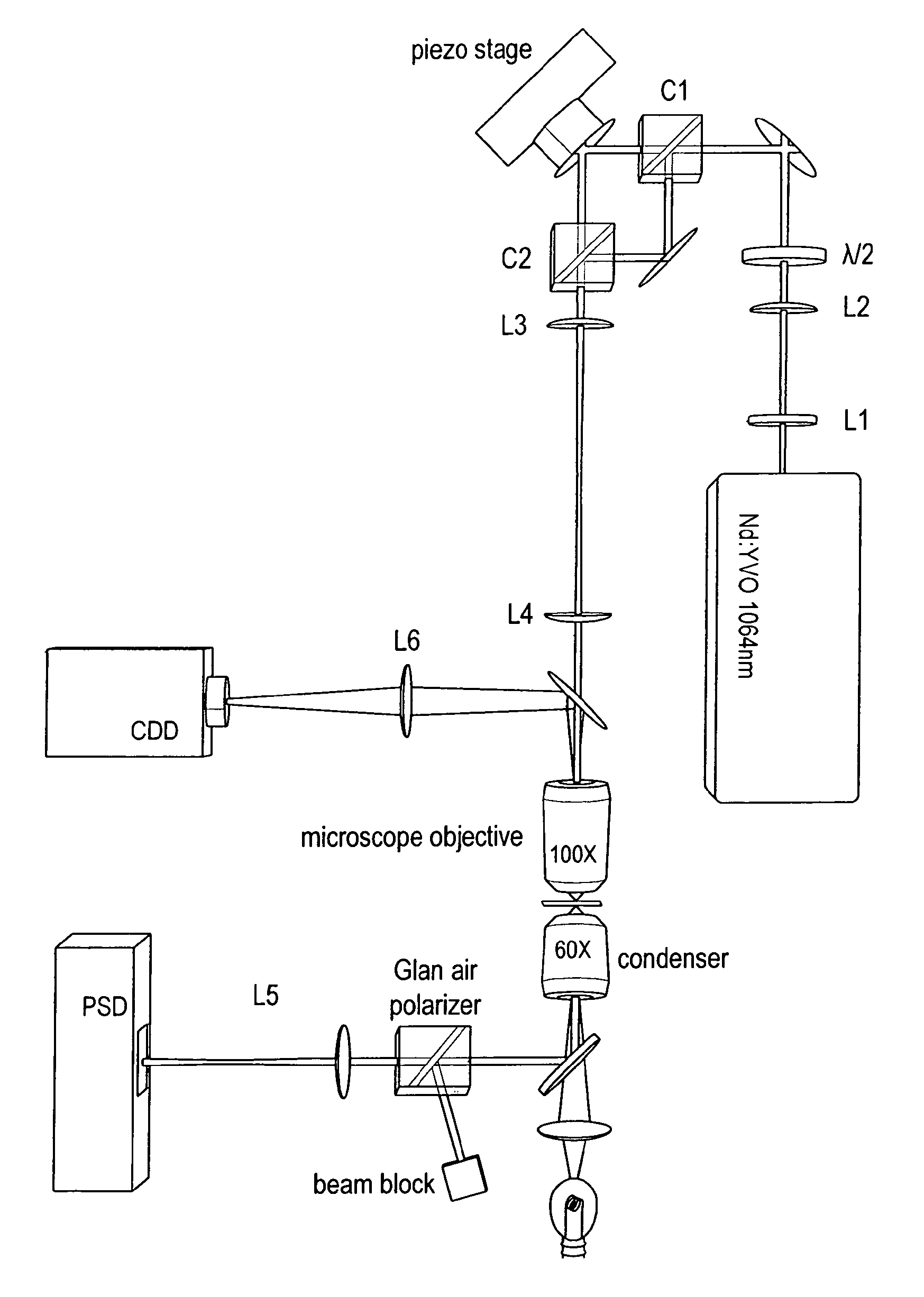
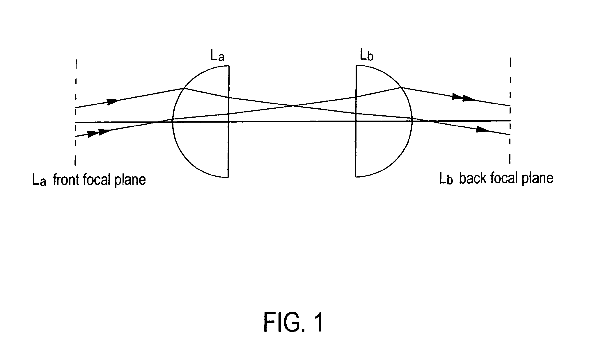
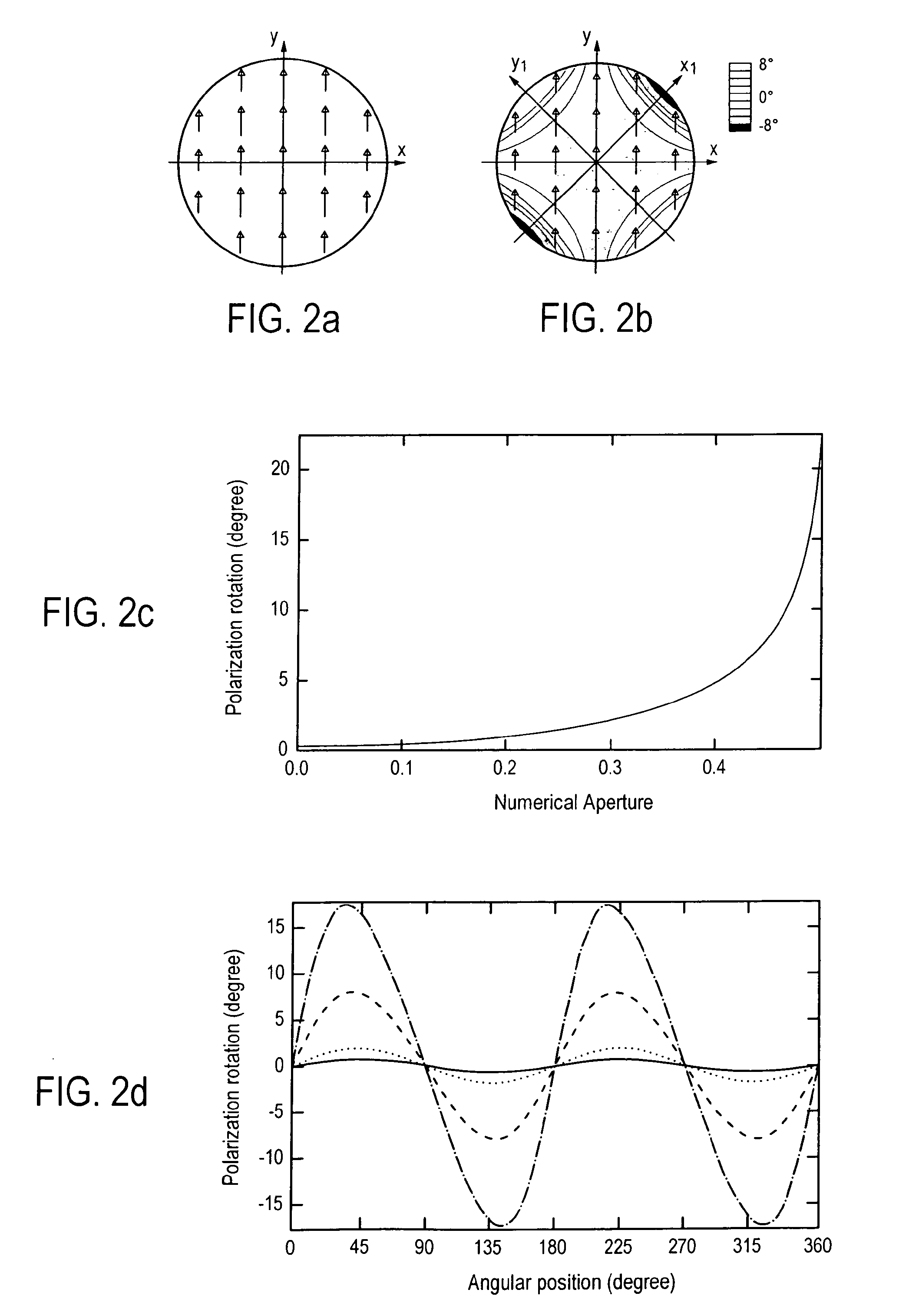
[0021]In a first part, we are going to discuss the rotation of polarization in a microscope. Conventional polarizing microscopy suffers from the rotation of polarization on lens surfaces or slides, which results in a loss of contrast when imaging a sample. A simple explanation of the rotation of polarization can be given as follows. For a linearly polarized beam refracting on the surface of a lens, the electric field exhibits different parallel and perpendicular components relative to the plane of incidence, depending on the position on the lens. Since, according to the Fresnel equations, the two components are refracted differently, the polarization of the total electric field is rotated. As described in more detail in the following description, this effect induces difficulties when detecting force with double optical tweezers.

[0022]For sake of simplicity, the propagation of light is described in a simple model, to give a qualitative understanding of the effects coming from the rot...


PUM


Abstract

Experimental studies of single molecule mechanics require high force sensitivity and low drift, which can be achieved with optical tweezers through an optical tweezers apparatus for force measurements. A CW infrared laser beam is split by polarization and focused by a high numerical aperture objective to create two traps. The same laser is used to form both traps and to measure the force by back focal plane interferometry. Although the two beams entering the microscope are designed to exhibit orthogonal polarization, interference and a significant parasitic force signal occur. Comparing the experimental results with a ray optics model, the interference patterns are caused by the rotation of polarization on microscope lens surfaces and slides. Two methods for reducing the crosstalk are directed to polarization rectification by passing through the microscope twice and frequency shifting of one of the split laser beams.

Description

TECHNICAL FIELD[0001]The invention relates to a method for reducing or minimizing interference and / or crosstalk that may appear in an apparatus comprising a double optical tweezers using a single laser source.BACKGROUND OF THE INVENTION[0002]Optical tweezers have been used over the two past decades to probe biological objects of various sizes, from whole cells down to individual proteins. Force measurement devices based on double optical tweezers have initially been used to manipulate non spherical particles such as bacteria, and increasingly became an important tool for single molecule studies of nucleic acids, and their interactions with proteins.[0003]An important feature of double optical tweezers derived from a single laser source is that, although the absolute position of each trap is sensitive to external mechanical perturbations, their relative position can be precisely imposed. Beam steering may be achieved with galvanometer, piezoelectric tilt mount or acousto-optic deflec...

Claims


Application Information

Patent Timeline
IPC IPC(8): H01S3/00
CPCG21K1/006
Inventor BOCKELMANN, ULRICHMANGEOL, PIERRE
Owner CENT NAT DE LA RECHERCHE SCI
Why Eureka
Try Eureka