Continuous, non-invasive, optical blood pressure monitoring system

a blood pressure monitoring and optical technology, applied in the field of blood pressure monitoring systems, can solve the problems of requiring medical staff to administer, invasive, time-consuming and patient discomfort,

Active Publication Date: 2011-07-21
BALDWIN DONNA +1
View PDF16 Cites 12 Cited by
  • Summary
  • Abstract
  • Description
  • Claims
  • Application Information

AI Technical Summary

Problems solved by technology

The most common manual and automated blood pressure monitors involve inflating and deflating a cuff and is both time consuming and involves some discomfort for the patient.
While these techniques provide a means of measuring blood pressure continuously, and are useful in operative settings, they are invasive, expensive, require medical staff to administer, and are not designed for continuous every day operations.
Calibration is extremely difficult for this type of sensor, and therefore is not expected to provide accurate or reproducible readings.
While this technique provides a means of measuring blood pressure in a cuff-less, non invasive setting, it requires prior calibration by the patient, and does not provide the same level of accuracy as other methods.
The abovementioned prior art lacks the advantages of a continuous blood pressure monitoring system that is capable of being worn for continual periods, whilst offering the patient complete mobility.

Method used


Image

  • Continuous, non-invasive, optical blood pressure monitoring system
  • Continuous, non-invasive, optical blood pressure monitoring system
  • Continuous, non-invasive, optical blood pressure monitoring system

Examples


Embodiment Construction

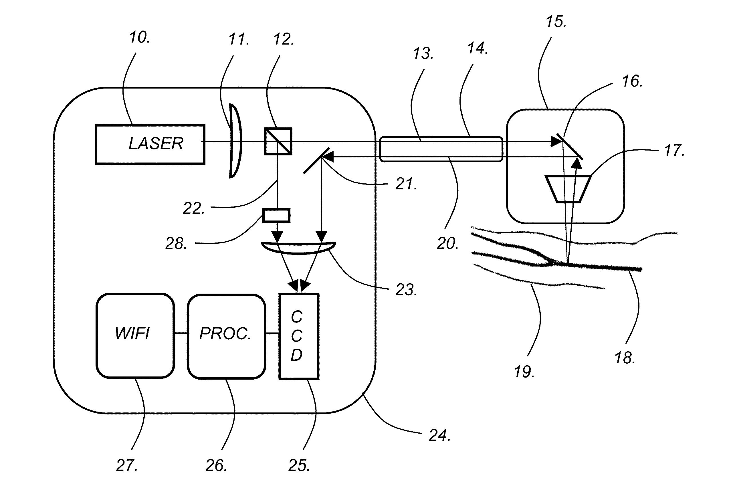
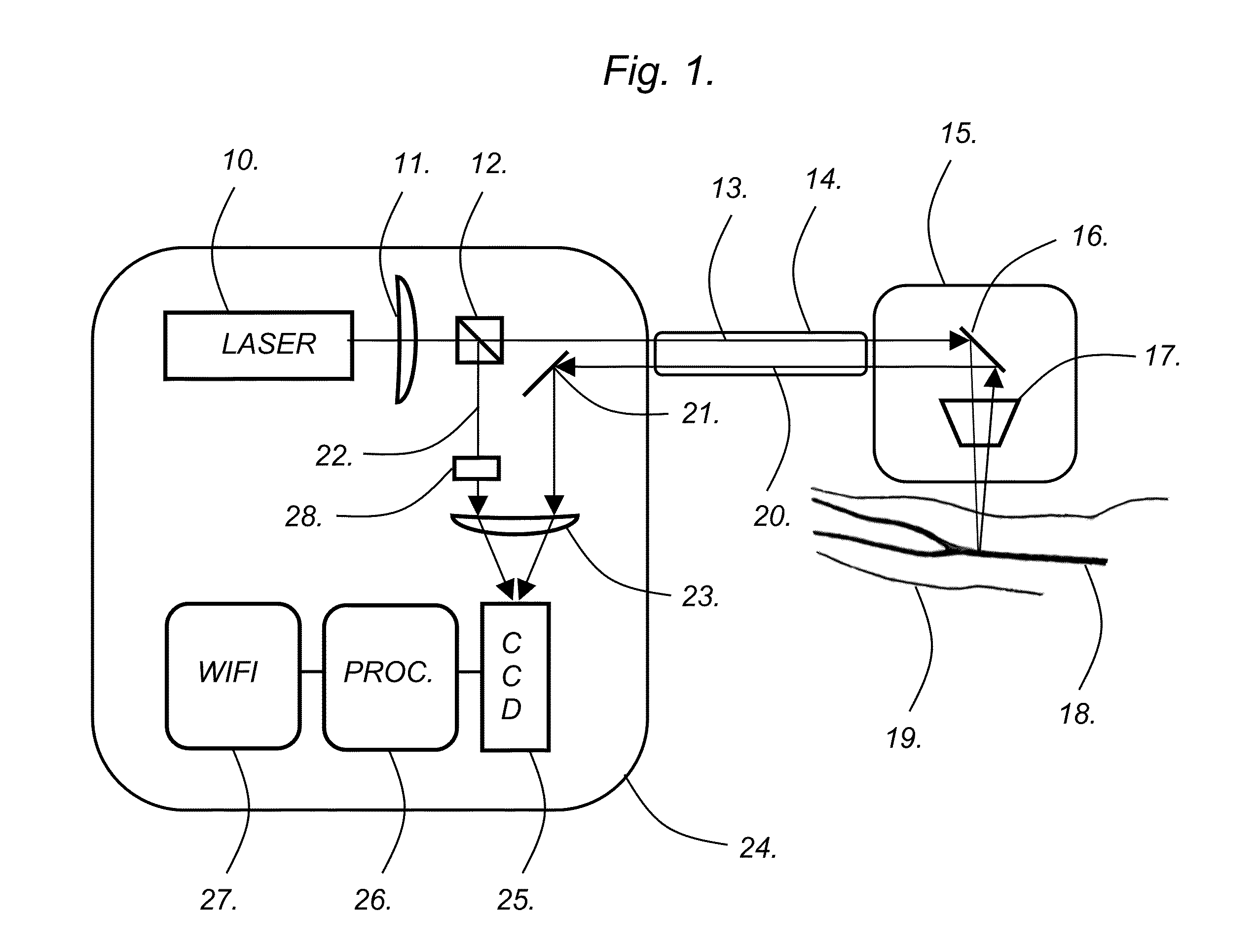
In accordance with the present invention, and with reference to FIG. 1, holographic interferometry is used to measure the time dependent variation of a patient's blood pressure. Blood pressure variation is recorded in the form of successive holographic infererometric fringe patterns during the beat cycle of the heart.

In prior art, a typical arrangement for recording a hologram involves a source of collimated light from a laser that is split into two coherent beams with a beam splitter. One of the beams, termed the object beam, illuminates an object and the light is refocused onto a photographic plate. The second beam, termed the reference beam, is focused directly onto the photographic plate. The light from both beams combines at the plate to form an interference pattern called a hologram. A hologram stores the complete amplitude and phase information of the illuminated object in such a way that re-illumination of the hologram, by the reference beam alone, produces a complete three ...


PUM


Abstract

The invention comprises a system of wearable devices that collectively allow for the continuous, non-invasive, measurement and monitoring of blood pressure, without the use of an inflatable cuff. The system incorporates: 1) An optical module, which is comprised of a coherent source of light, a semi-transparent hologram, microscope optics for viewing the interference pattern developed between the illuminated hologram and arterial blood, a spatial light modulator (SLM), and processing electronics with Bluetooth capability that facilitates digitization and wireless transmission of the fringe pattern to, 2) a personal digital assistant (PDA) that is worn on a waist belt. The PDA and associated software allow for continuous calculation and monitoring of real-time arterial blood pressure from the digitized fringe patterns received. The system further comprises 3) a personal computer (PC) with wireless capacity and connection to the internet. Continuous BP function, alerts, condition and medical assessment is conducted through PDA-PC communications with internet based medical facility.

Description

FIELD OF INVENTIONThe present invention relates to blood pressure monitoring systems. More specifically, the present invention relates to a non-invasive, wearable, cuff-less blood pressure system having optical and wireless components.BACKGROUND OF THE INVENTIONCardiac contraction during a heartbeat causes a time dependent flow of blood in the arteries of the body. The flow of blood in a single beat is pulse-like and caused by a rise in the pressure of the blood from a static value, called the diastolic pressure, to a maximum value at the peak of the pulse, called the systolic pressure. The pulse-like variation in blood pressure induces a corresponding pulse-like variation in the refractive index of the blood plasma. That is, the variation of blood pressure in a heart beat induces a variation in the optical properties of the blood.Conventional blood pressure monitoring devices typically involve measuring blood pressure with an inflatable cuff, whether automated, or by manual inflati...

Claims


Application Information

Patent Timeline
Patent Type & Authority Applications(United States)
IPC IPC(8): A61B5/021
CPCA61B5/0059A61B5/024A61B5/021
Inventor BALDWIN, DONNABALDWIN, MATTHEW JAMES
Owner BALDWIN DONNA
Why Eureka
Try Eureka